Two-axis orthogonal rotation system and method for CVD equipment

A kind of technology of equipment and rotating shaft, which is applied in the direction of metal material coating process, coating, gaseous chemical plating, etc., can solve the problems of poor deposition quality and stability of epitaxial layer, and cannot be effectively controlled, so as to improve coating quality and production Efficiency, improvement of flow velocity distribution, and effect of improving CVD efficiency

Active Publication Date: 2020-11-06
NORTHWESTERN POLYTECHNICAL UNIV
View PDF13 Cites 0 Cited by
  • Summary
  • Abstract
  • Description
  • Claims
  • Application Information

AI Technical Summary

Problems solved by technology

[0005] In order to avoid the deficiencies of the prior art, the present invention proposes a two-axis orthogonal rotation system for CVD equipment, by controlling the components to rotate in two dimensions in the CVD deposition furnace body, so that different parts of the components are in uniform contact with the gas , can break the bottleneck of existing CVD equipment, achieve uniform deposition conditions, and greatly improve the uniformity, compactness and interface bonding force of the epitaxial layer, thereby solving the problem of poor deposition quality and stability of the epitaxial layer of components, especially large-scale and complex components. Unable to effectively control and other technical problems to achieve uniform and controllable preparation of high-performance epitaxial layers

Method used


Image

  • Two-axis orthogonal rotation system and method for CVD equipment
  • Two-axis orthogonal rotation system and method for CVD equipment
  • Two-axis orthogonal rotation system and method for CVD equipment

Examples


Embodiment 1

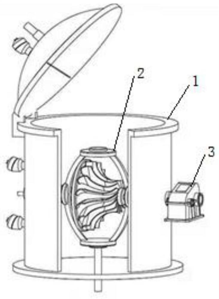
[0042] refer to figure 1 , 2 and 9, the central position of the constant temperature zone in the CVD deposition furnace body 1 is set as the coordinate origin, the xoy plane of the coordinates is perpendicular to the central axis of the constant temperature zone, and the z axis of the coordinates coincides with the central axis of the constant temperature zone; Three sleeves 13 pass through the CVD deposition furnace furnace body 1 and the graphite insulation pipe 11 along the positive and negative directions of the coordinate X axis and the negative direction of the Z axis respectively, and one end of the three sleeves 13 is connected to the CVD deposition furnace furnace body 1 respectively. Seamlessly welded, the other end is respectively fixed and sealed with the graphite insulation pipe 11, such as connected by threaded rotation;

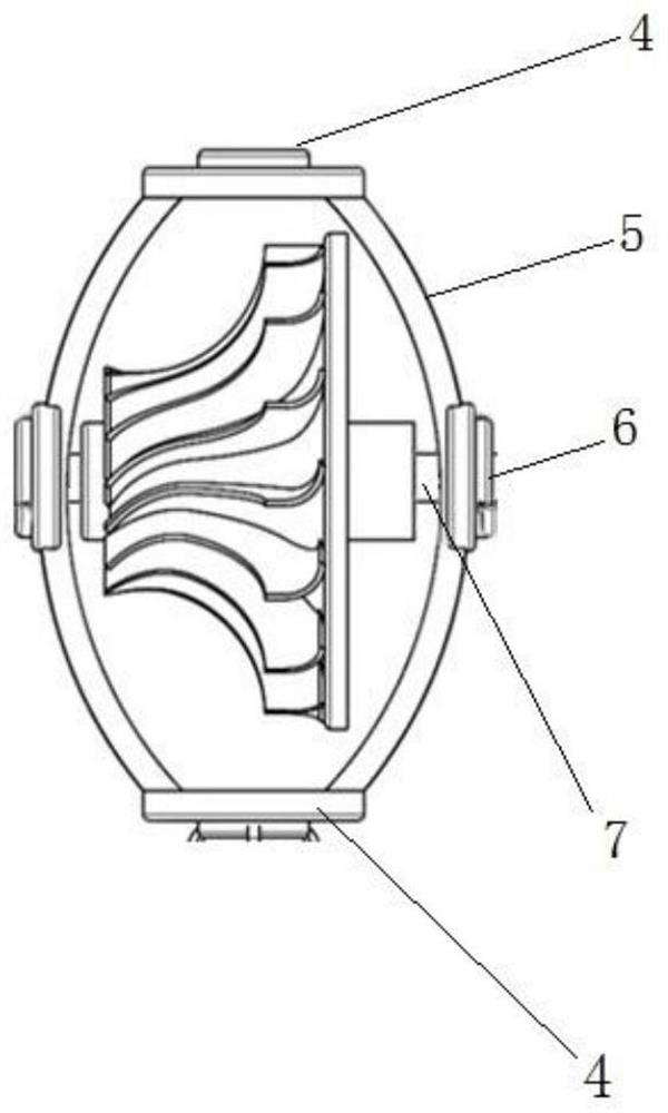
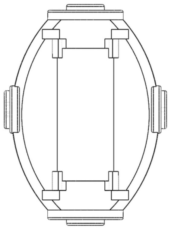
[0043] The component fixture 2 is a hollowed-out frame structure, which is used to fix and install the deposited component. The center point ...

Embodiment 2

[0045] refer to figure 1 , 3 and 9, the central position of the constant temperature zone in the CVD deposition furnace body 1 is set as the coordinate origin, the xoy plane of the coordinates is perpendicular to the central axis of the constant temperature zone, and the z axis of the coordinates coincides with the central axis of the constant temperature zone; Three sleeves 13 pass through the CVD deposition furnace furnace body 1 and the graphite insulation pipe 11 along the positive and negative directions of the coordinate X axis and the negative direction of the Z axis respectively, and one end of the three sleeves 13 is connected to the CVD deposition furnace furnace body 1 respectively. Seamlessly welded, the other end is respectively fixed and sealed with the graphite insulation pipe 11, such as connected by threaded rotation;

[0046] The component fixture 2 is a hollowed-out frame structure, which is used to fix and install the deposited component. The center point ...

Embodiment 3

[0049] refer to figure 1 , 5 and 9, the central position of the constant temperature zone in the CVD deposition furnace body 1 is set as the coordinate origin, the xoy plane of the coordinates is perpendicular to the central axis of the constant temperature zone, and the z axis of the coordinates coincides with the central axis of the constant temperature zone; Three sleeves 13 pass through the CVD deposition furnace furnace body 1 and the graphite insulation pipe 11 along the positive and negative directions of the coordinate X axis and the negative direction of the Z axis respectively, and one end of the three sleeves 13 is connected to the CVD deposition furnace furnace body 1 respectively. Seamlessly welded, the other end is respectively fixed and sealed with the graphite insulation pipe 11, such as connected by threaded rotation;

[0050] The component fixture 2 is a hollowed-out frame structure, which is used to fix and install the deposited component. The center point ...


PUM


Abstract

The invention discloses biaxial orthogonal rotation system for CVD equipment. The biaxial orthogonal rotation system comprises a CVD deposition furnace body, graphite thermal insulation pipes, a heating body, rotating shafts, a sleeve, a component clamp and rotary power devices; the three rotary power devices are connected with the component clamp arranged in the CVD deposition furnace body through the three rotating shafts; the rotary power devices are used for providing power for the whole system, controlling the rotating speed and the telescopic positions of the rotating shafts, and furthercontrolling the component clamp to rotate around X axis or rotate around Y axis; and different rotation directions are adopted in different deposition stages, so that a position with insufficient deposition of a complex-shaped component can be compensated to a greater extent. By adopting different rotational speeds, velocity distribution of surrounding gas of the component relative to the component can be improved, so that the relative flowing velocity distribution is most beneficial to obtain uniform deposition.

Description

technical field [0001] The invention belongs to the field of chemical vapor deposition (CVD) equipment, and in particular relates to a dual-axis orthogonal rotation system and method for CVD equipment. Background technique [0002] The preparation of epitaxial layer materials represented by anti-oxidation and ablation ceramic coatings is inseparable from CVD (Chemical Vapor Deposition, chemical vapor deposition) equipment. CVD is to generate a non-volatile solid product at a certain temperature through the pyrolysis and reduction of a certain gas phase precursor and deposit it on the surface of the substrate to achieve the purpose of forming a coating. This method has the advantages of simple deposition equipment, low preparation temperature, high purity of the prepared coating, and controllable structure. Because the reactants interact in the gas phase in the deposition chamber, the CVD method has better wrap-around properties than other methods. At the same time, since C...

Claims


Application Information

Patent Timeline
Patent Type & Authority Patents(China)
IPC IPC(8): C23C16/458
Inventor 李贺军李博张雨雷刘宁坤姚西媛付前刚史小红
Owner NORTHWESTERN POLYTECHNICAL UNIV
Why Eureka
Try Eureka