Walking method of pipeline robot

A pipeline robot and pipeline technology, which is applied to the walking field of pipeline robots, can solve problems such as the inability to change the thickness, the inability to turn the pipeline, and the limitation of the application of pipeline robots.

Active Publication Date: 2019-05-17
桐乡市高德工程技术服务有限公司
View PDF6 Cites 6 Cited by
  • Summary
  • Abstract
  • Description
  • Claims
  • Application Information

AI Technical Summary

Problems solved by technology

[0007] The purpose of the present invention is to provide a walking method for a pipe robot, which solves the problem that the existing pipe robot cannot cope with some special-shaped pipes, and cannot change the thickness, and cannot enter a thin pipe from a thick pipe, so the applicable size is very large. The limitations of the pipeline, and the pipes with different curvatures cannot be turned, which leads to the problem that the application of the pipeline robot is limited.

Method used


Image

  • Walking method of pipeline robot
  • Walking method of pipeline robot
  • Walking method of pipeline robot

Examples


specific Embodiment approach 1

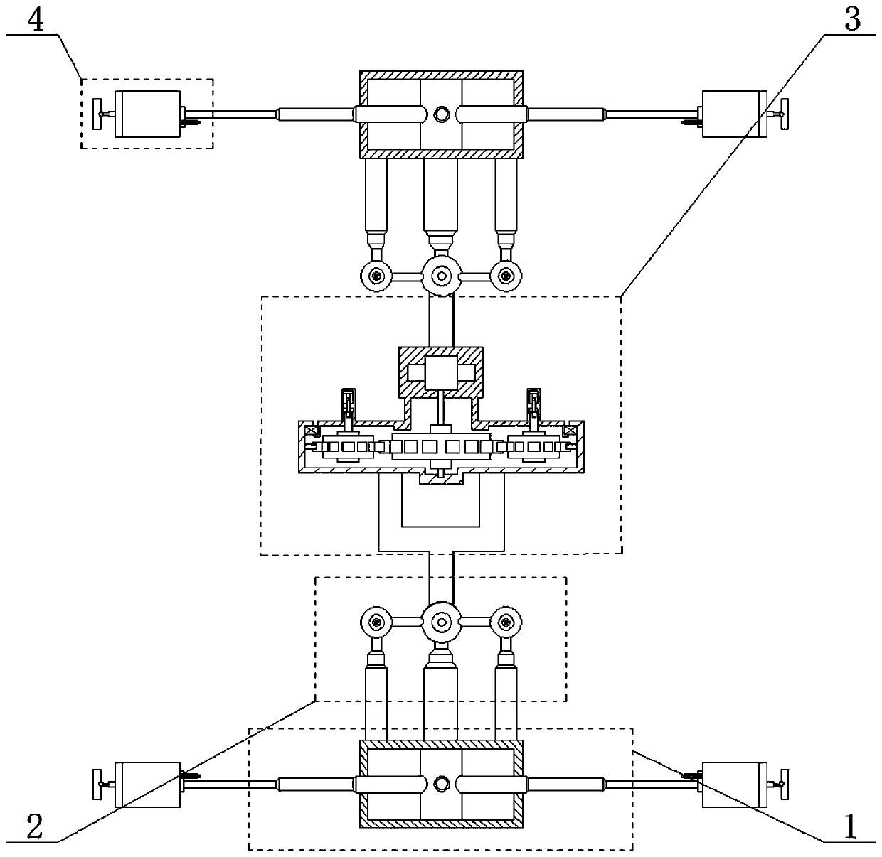
[0067] Such as figure 1 As shown, a pipeline robot disclosed in this embodiment includes: an extension drive device 1, a first steering drive device 2, a second steering drive device 3 and a foot 4; both ends of the second steering drive device 3 are connected to The movable end of a first steering drive device 2 is fixedly connected, and the fixed end of each first steering drive device 2 is fixedly connected with one end of an extension drive device 1, and a plurality of legs 4 are hinged on the extension drive device 1;

[0068] The first steering drive device 2 has a turning function and a telescopic function, and can drive the second steering drive device 3 to perform a turning movement. The first steering drive device 2 can drive the stretching drive device 1 to move through stretching. The stretching drive device 1 has a telescopic function. A steering drive device 2 is combined with the stretching drive device 1 to complete the action of entering the thin pipe from the...

specific Embodiment approach 2

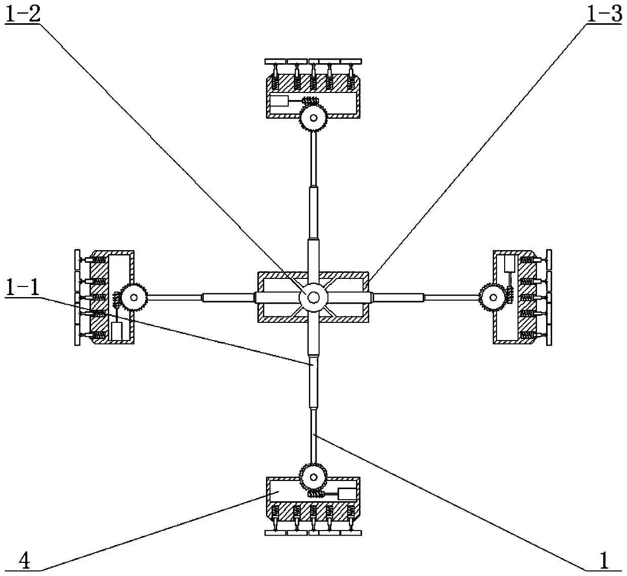
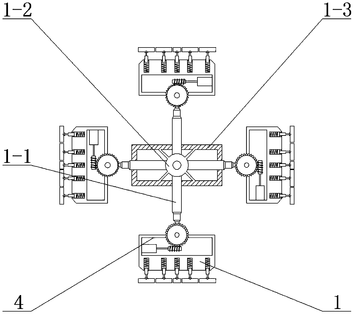
[0070] to combine Figure 1 to Figure 4 , this embodiment is based on the first specific embodiment, the difference is that: the first steering drive device 2 includes: a first telescopic rod 2-1, a second telescopic rod 2-2 and a steering drive rod 2-3; The fixed end of the first telescopic rod 2-1 is fixedly connected to the outer surface of the stretching drive device 1, and the two second telescopic rods 2-2 are arranged in parallel on the outer surface of the stretching drive device 1 and are located on the first telescopic rod 2. On both sides of -1, the fixed ends of the two second telescopic rods 2-2 are fixedly connected to the outer surface of the extension drive device 1, and the steering drive rod 2-3 is provided with multiple connection ends, and the first telescopic rod 2-1 The movable end of the two telescopic rods 2-2 is rotationally connected with the connection end located in the middle of the steering drive rod 2-3, and the movable ends of the two second tel...

specific Embodiment approach 3

[0072] to combine Figure 1 to Figure 4 , this embodiment is based on the second specific embodiment, the difference is that: the extension drive device 1 includes: a third telescopic rod 1-1, a fixed block 1-2 and a first housing 1-3; the first One end of the housing 1-3 is fixedly connected to the fixed end of the first telescopic rod 2-1 and the second telescopic rod 2-2, and the first housing 1-3 is fixedly connected with a fixed block 1-2 inside, and the fixed block 1- 2. A plurality of third telescopic rods 1-1 are welded symmetrically, the fixed ends of the third telescopic rods 1-1 are welded on the surface of the fixed block 1-2, and each movable end of the third telescopic rods 1-1 is hinged with a Leg 4;

[0073] The fixing block 1-2 plays a role of fixing each third telescopic rod 1-3. After the present invention is placed in the pipeline, all the third telescopic rods 1-3 drive each leg 4 to extend outward through elongation, even though each leg 4 is attached t...


PUM


Abstract

The invention belongs to the technical field of pipeline robots, and particularly relates to a walking method of a pipeline robot. The walking method of the pipeline robot includes a method of the pipeline robot fitting pipeline walls, a method of the pipeline robot walking in pipelines and a method of the pipeline robot making a turn in the pipelines. The walking method of the pipeline robot cansolve the problems that existing pipeline robots cannot cope with pipelines with special shapes, cannot change the thickness, and cannot enter thin pipelines from thick pipelines, so that the applicable size has great limitations, making a turn cannot be carried out when the pipelines with different bending degrees are handled, and the limitation of the application of the pipeline robots is caused.

Description

technical field [0001] The invention belongs to the technical field of pipeline robots, and in particular relates to a walking method of pipeline robots. Background technique [0002] Pipeline robot is a kind of machine, electricity and instrument that can walk automatically along the inside or outside of a small pipeline, carry one or more sensors and operating machinery, and perform a series of pipeline operations under the remote control of the staff or the automatic control of the computer. The existing pipeline robot cannot cope with some situations as follows: [0003] (1) It is impossible to enter pipelines with special cross-sectional shapes; [0004] (2) The thickness cannot be changed, and it is impossible to enter the thin pipe from the thick pipe, so the applicable size is limited; [0005] (3) Pipelines with different curvatures cannot be turned, which limits the application of pipeline robots; [0006] (4) It is impossible to avoid the problem that the pipel...

Claims


Application Information

Patent Timeline
Patent Type & Authority Applications(China)
IPC IPC(8): F16L55/32B25J11/00
Inventor 任成
Owner 桐乡市高德工程技术服务有限公司
Why Eureka
Try Eureka