A fiber ring curing pretreatment equipment

An optical fiber ring and pretreatment technology, which is used in instruments, measuring devices, Sagnac effect gyroscopes, etc., can solve the problems of uneven distribution of the ring glue in the ring, affecting the yield of the ring, and reduce the unstable rotation. performance, solve the inability to adjust, and increase the effect of programmable control functions

Active Publication Date: 2020-08-28
北京联智信达科技有限公司
View PDF10 Cites 0 Cited by
  • Summary
  • Abstract
  • Description
  • Claims
  • Application Information

AI Technical Summary

Problems solved by technology

[0005] The purpose of the present invention is to carry out the glue homogenization operation on the optical fiber ring that has just been wound and has not been cured, so as to solve the problem that the ring glue is not evenly distributed in the ring and affects the ring yield after the optical fiber winding is completed.

Method used


Image

  • A fiber ring curing pretreatment equipment
  • A fiber ring curing pretreatment equipment

Examples


Embodiment Construction

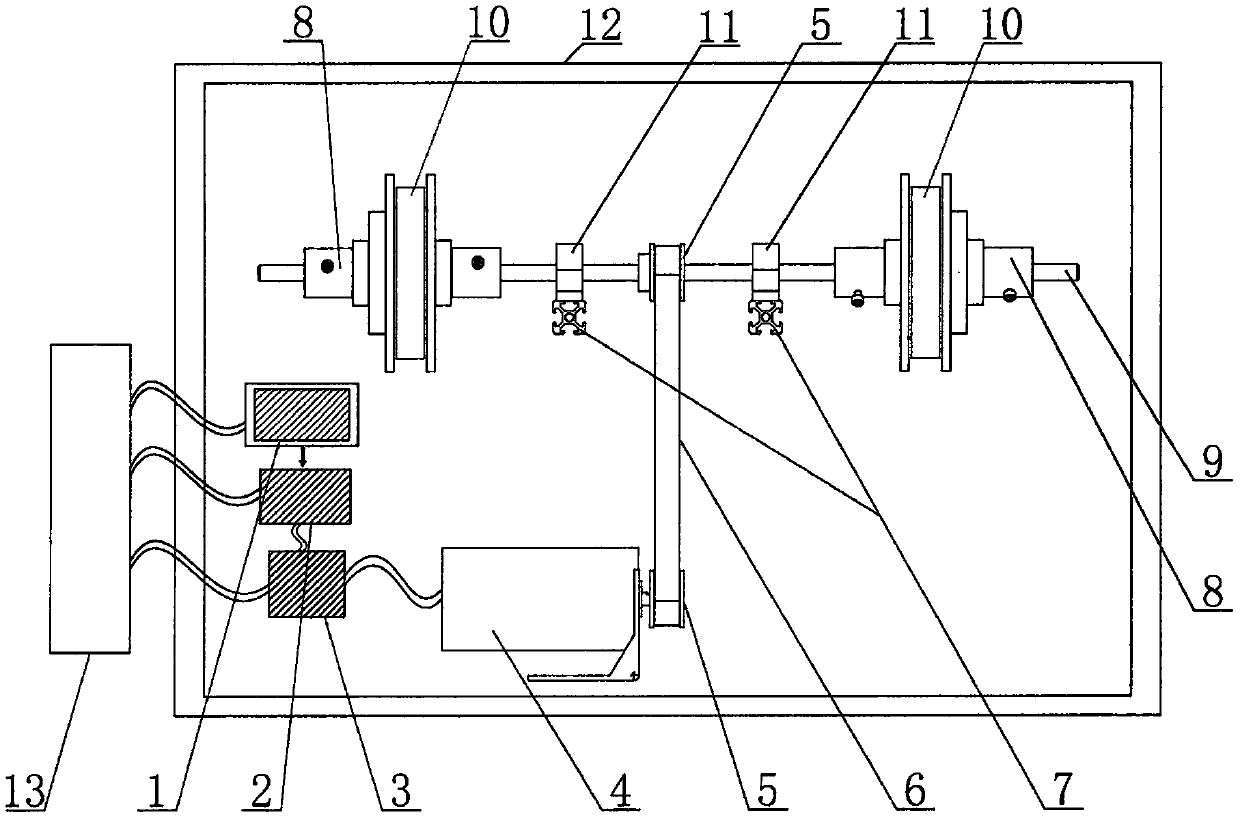
[0021] The structure of the optical fiber ring curing pretreatment equipment is as follows: figure 1 shown. The frame 7 and the housing 12 are used as the support of the whole device to install and fix other components. The motor 4 is installed on the bottom of the frame 7 and its front, rear, left, and right positions are adjustable. Two synchronous wheels 5 are respectively connected with the motor 4 and the rotating shaft 9. The synchronous belt 6 is connected with the two synchronous wheels 5 to realize the synchronous rotation of the motor 4 and the rotating shaft 9. , the motor 4 can move back and forth to adjust the tightness of the synchronous belt 6 installation. The rotating shaft 9 is supported by bearing blocks 11 at a certain distance, and the bearing blocks 11 are installed above the frame 7. The two ends of the rotating shaft 9 protrude in an open form, and two tooling fixtures 8 can be installed in a symmetrical form on both sides of the rotating shaft. An op...


PUM


Abstract

The invention belongs to optical fiber ring curing pretreatment equipment, and particularly relates to equipment for improving the optical fiber ring curing finished product rate. The equipment comprises a touch screen, a control module, a motor driver, a motor, a synchronizing wheel, a synchronizing belt, a machine frame, a tooling clamp tool, a rotating shaft, optical fiber rings, a bearing seat, a casing and a power supply module, wherein the touch screen is used for inputting motor rotating modes and operation parameters; the control module generates a practical rotation curve according tothe rotation mode and the operation parameters and controls the motor to move according to the curve; and the optical fiber rings are symmetrically arranged at the two sides of the rotating shafts. The device has a programmable control function of the rotating mode; and the rotation of the optical fiber rings according to the specified rotating speed, angle, duration and specific rotating mode can be realized. The equipment provided by the invention has the beneficial effects that through the addition of a synchronizing belt rotating mechanism, the problem of radial runout generated when an existing shaft coupler is connected with the rotating shaft to rotate is solved; the rotating shaft is provided with the two optical fiber rings in a two-side extending mode; the rotation movement instability when the two optical fiber rings are arranged at the single side of the rotating shaft is reduced; a programmable control module is added, so that the programming control on the optical fiberring rotating state can be realized; the problems that during the still standing of the optical fiber rings in the prior art, the speed and the time cannot be regulated can be solved; and the glue uniformity during the still standing of the optical fiber rings is improved.

Description

[technical field] [0001] The invention belongs to optical fiber ring curing pretreatment equipment in the field of optical fiber sensing, and in particular relates to a device for improving the curing yield and efficiency of optical fiber rings. [Background technique] [0002] The fiber optic ring is the core component of the fiber optic gyroscope, and its production quality plays a decisive role in the performance of the fiber optic gyroscope. The optical fiber ring is made by regularly winding the sensitive optical fiber with sensitive optical fiber, ring-wrapping glue and specific ring-wrapping process. In the process of optical fiber winding, methods such as winding with glue or late glue filling are usually used to make the ring glue penetrate into the optical fiber ring, and the sensitive optical fiber is fully bonded to ensure the structural strength of the optical fiber ring. [0003] However, no matter which method is used, it is difficult to ensure the uniform dis...

Claims


Application Information

Patent Timeline
Patent Type & Authority Patents(China)
IPC IPC(8): G01C25/00G01C19/72
Inventor 李瑞刘谦哲付常亮李晓治王飞邱玥
Owner 北京联智信达科技有限公司
Why Eureka
Try Eureka