
Digital regulation bias current source

A bias current source and digital technology, applied in the direction of adjusting electrical variables, control/regulation systems, instruments, etc., can solve problems such as limited adjustment range and poor adjustment accuracy in large ranges

Active Publication Date: 2019-05-17
SHANGHAI PANCHIP MICROELECTRONICS CO LTD
View PDF15 Cites 6 Cited by
  • Summary
  • Abstract
  • Description
  • Claims
  • Application Information

AI Technical Summary

Problems solved by technology

[0005] In view of the above-mentioned defects of the prior art, the technical problem to be solved by the present invention is how to eliminate the shortcomings of poor wide-range adjustment accuracy and limited adjustment range in traditional active bias circuits

Method used


Image

  • Digital regulation bias current source
  • Digital regulation bias current source
  • Digital regulation bias current source

Examples


Embodiment Construction

[0023] The following describes the preferred embodiments of the present invention with reference to the accompanying drawings to make the technical content clearer and easier to understand. The present invention can be embodied in many different forms of embodiments, and the protection scope of the present invention is not limited to the embodiments mentioned herein.

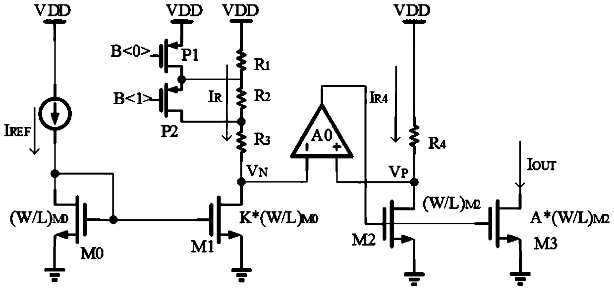
[0024] Such as image 3 As shown, a digitally adjusted bias current source in a preferred embodiment of the present invention includes a first current mirror, an operational amplifier A0, a resistance adjustment network, and a second current mirror, and the output terminal of the first current mirror is passed through The resistance adjustment network is connected to the power supply VDD, the inverting input terminal of the operational amplifier A0 is connected to the output terminal of the first current mirror, and the non-inverting input terminal of the operational amplifier A0 is connected to the output termi...


PUM


Abstract

The invention discloses a digital regulation bias current source, and relates to the technical field of the bias current source design in the integrated circuit. The digital regulation bias current source comprises a first current mirror, an operational amplifier, a resistance regulation network, a second current mirror; an output end of the first current mirror is connected to a power supply through the resistance regulation network, a reverse-phase input end of the operational amplifier is connected with the output end of the first current mirror, an in-phase input end of the operational amplifier is connected with an input end of the second current mirror, the output end of the operational amplifier is connected with a control end of the second current mirror, and the input end of the second current mirror is connected to the power supply through a resistive element. By importing the operational amplifier and utilizing the short circuit principle thereof, the digital regulation biascurrent source provided by the invention can realize the current precise duplication in an assistant way, the control is realized by utilizing a digital logic level control bus, and the wide-range regulation of the mirror current is realized.

Description

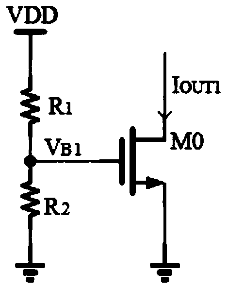
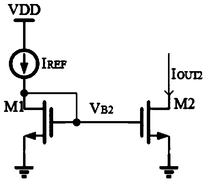
technical field [0001] The invention relates to the technical field of bias current source design in analog integrated circuits, in particular to a digitally adjusted bias current source. Background technique [0002] Most current sources are conventional passive and active bias circuit structures. [0003] In conventional analog bias circuit configurations, such as figure 1 As shown, the principle of the passive bias circuit is resistor divider: VDD is the supply voltage. Its characteristic is that the circuit is simple and has high precision. However, if the voltage dividing resistor is small, the circuit consumes a large amount of current although the area is small. If the voltage dividing resistor is added, the current consumption can be reduced but it occupies a larger area. In addition, the resistor divider circuit can only provide an appropriate bias voltage but cannot provide a bias current. The NMOS transistor M0 is at the bias voltage V B1 Under the action of ...

Claims


Application Information

Patent Timeline
Patent Type & Authority Applications(China)
IPC IPC(8): G05F3/26
Inventor 王利曹裕荣
Owner SHANGHAI PANCHIP MICROELECTRONICS CO LTD
Learn More