A wide range adjustable analog load device
A load-simulating, large-scale technology, applied in the direction of measuring devices, machine/structural component testing, engine testing, etc., can solve the problems of long cycle, prolonging the development cycle of valve devices, and the inability to realize the rapid application of valve devices, etc.
- Summary
- Abstract
- Description
- Claims
- Application Information
AI Technical Summary
Problems solved by technology
Method used
Image
Examples
Embodiment 1
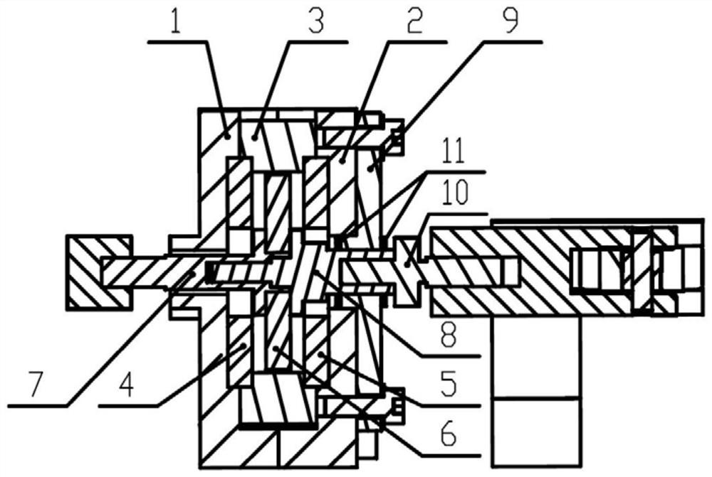
[0028] refer to figure 1 , is a sectional view of the internal structure of a large-range adjustable simulated load device of the present invention. The invention discloses a large-scale adjustable analog load device, which comprises: a load frame, an automatic loading device, a mechanical transmission device and a limit device. The automatic loading device, mechanical transmission device and limit device are installed and fixed through the load frame; the automatic loading device is installed in the load frame; the mechanical transmission device is set at the horizontal central axis of the load frame, passing through the load frame and the automatic loading device; the mechanical transmission device is provided with a limit device to limit the movement path of the mechanical transmission device.
[0029] In this embodiment, the load frame includes: a load frame 1 at the left end, a load frame 2 at the right end, and a pressing plate 3 . The left end load frame 1 and the rig...
Embodiment 2
[0037] In the specific implementation process of the matching valve debugging work of the large-scale adjustable analog load device disclosed by the present invention, its specific implementation flow includes two stages: a positioning process and a control process.
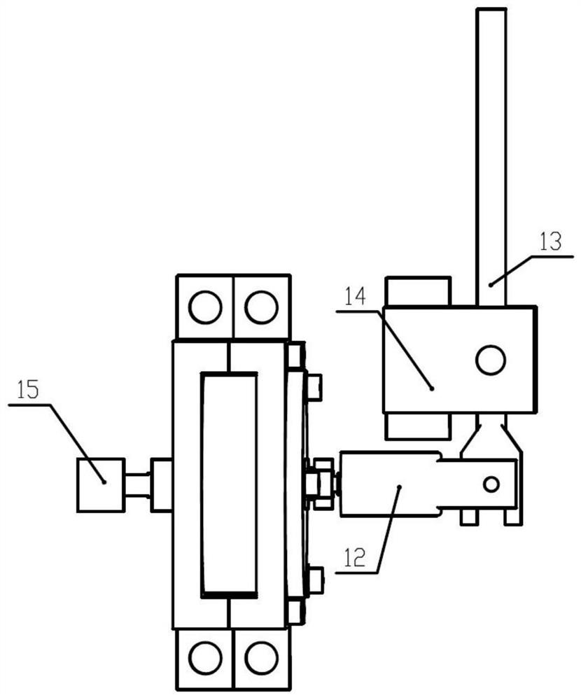
[0038] The location-finding process flow is as follows: the overall device is fixed by a fixed tool, the first permanent magnet 4 and the second permanent magnet 5 under the automatic loading device automatically add load to the force-bearing element 6, the pull rod 12 and the limit block 10 are connected by threads, and the lever 13 is connected with the frame 14 through the fulcrum pin, the end of the lever 13 is inserted into the center pin of the pull rod 12, and a certain load is manually applied to the end of the long arm of the lever 13, and the end of the lever 13 drives the pull rod 12 and the limit block 10 to move together, and the mechanical transmission The left guide rod 7, the right guide rod 8, and...
PUM
 Abstract
Description
Claims
Application Information
 - R&D
- Intellectual Property
- Life Sciences
- Materials
- Tech Scout
- Unparalleled Data Quality
- Higher Quality Content
- 60% Fewer Hallucinations
Browse by: Latest US Patents, China's latest patents, Technical Efficacy Thesaurus, Application Domain, Technology Topic, Popular Technical Reports.
© 2025 PatSnap. All rights reserved.Legal|Privacy policy|Modern Slavery Act Transparency Statement|Sitemap|About US| Contact US: help@patsnap.com


