LED lamp strip convenient for replacement of LED lamp beads

A technology of LED light strips and LED light beads, which is applied in the parts of lighting devices, semiconductor devices of light-emitting elements, lighting and heating equipment, etc., can solve problems such as personnel fatigue, potential safety hazards, and long distances for power switches.

Inactive Publication Date: 2020-07-28
何呈旺
View PDF0 Cites 0 Cited by
  • Summary
  • Abstract
  • Description
  • Claims
  • Application Information

AI Technical Summary

Problems solved by technology

[0003] In view of the above, the current lamp beads are soldered to the light bar by soldering. To overhaul it, the light bar needs to be removed, and the internal lamp beads should be desoldered and replaced. However, during the process of desoldering, the staff will accidentally Touching the nearby lamp beads will cause secondary damage to them, and some power switches are far away from the light strips for maintenance. Fatigue, there will be safety hazards, the invention provides an LED light bar that is easy to replace the LED light beads

Method used


Image

  • LED lamp strip convenient for replacement of LED lamp beads
  • LED lamp strip convenient for replacement of LED lamp beads
  • LED lamp strip convenient for replacement of LED lamp beads

Examples


Embodiment 1

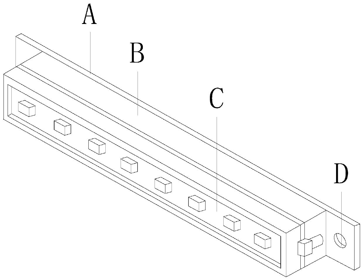
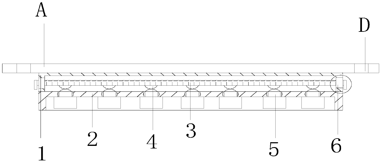
[0026] Such as Figure 1-Figure 4 Shown:

[0027] The present invention provides an LED light bar for easy replacement of LED lamp beads. Its structure includes a fixed plate A, a body B, a light bar mechanism C, and an auxiliary hole D. The fixed plate A is welded and connected to the bottom of the body B, and the auxiliary There are two holes D, and the auxiliary hole D is fixedly installed on both sides of the fixed plate A, characterized in that: the light bar mechanism C is embedded and connected inside the body B; the light bar mechanism C mainly includes a lower seat 1. Upper bearing 2, driving board 3, induction block 4, lamp bead device 5, sliding device 6, the upper bearing 2 is embedded and connected under the lower bearing 1, and the driving board 3 is movable through the sliding device 6 Closed in the middle of the lower seat 1, the induction block 4 is connected under the drive plate 3 with an interference fit, and the lamp bead device 5 is movably engaged and i...

Embodiment 2

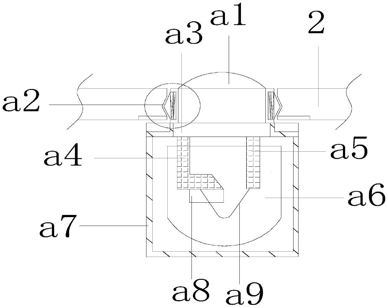
[0033] Such as Figure 5-Figure 8 Shown:

[0034] The present invention provides an LED light bar for easy replacement of LED lamp beads. The sliding device 6 mainly includes a fixed block 61, a moving groove column 62, and a push rod 63. The fixed block 61 is embedded and connected under the upper bearing 2. The moving slot column 62 is riveted and connected to the middle of the fixed block 61, and the push rod 63 is installed in the moving slot column 62 with clearance fit, and the push rod 63 is in interference connection with the drive plate 3. With the drive plate 3 in the middle as the midpoint, it has a left-right symmetrical structure, which conforms to ergonomics, and the simultaneous operation of both sides makes it easy to move.

[0035]Wherein, the moving groove column 62 mainly includes a connecting plate c1, an arc-shaped groove c2, and an auxiliary rolling c3, ​​the connecting plate c1 is provided with an arc-shaped groove c2, and the auxiliary rolling c3 is mo...


PUM


Abstract

The invention discloses an LED lamp strip convenient for replacement of LED lamp beads. The LED lamp strip structurally comprises a fixed plate, a machine body, a light strip mechanism and auxiliary holes. The light strip mechanism is fixedly connected into the machine body in an embedded mode; the light strip mechanism comprises a lower bearing seat, an upper bearing seat, a driving plate, induction blocks, a lamp bead device and sliding devices. The driving plate is movably clamped in the middle of the lower bearing seat through the sliding devices, and the lamp bead device is movably installed under the upper bearing seat in a clamped mode. The sliding devices are pushed upwards to disconnect the current between the induction blocks and contact heads, thus completing power failure operation, and solving the problem that a worker needs to remotely switch a power supply. The lamp bead device is pulled downwards to take out the lamp bead device, and then lamp beads needing to be replaced are pressed upwards to the original position, therefore the situation that replacement can be conducted only by overall disassembly is solved.

Description

technical field [0001] The present invention relates to the field of LED lighting, and more specifically, relates to an LED light bar for easy replacement of LED light beads. Background technique [0002] LED light bar is a kind of lighting equipment that uses a variety of materials. It can be used in display cabinets, bedside tables and other places. After the LED light bar is used for a long time, the lamp beads inside the light bar will be reduced due to failure or aging of the wick. The brightness of the lighting, so it needs to be repaired. The current lamp beads are welded on the lamp bar by soldering. In the process, the staff will touch the nearby lamp beads due to negligence, causing secondary damage to them, and some power switches are far away from the light bars for maintenance. Continuous walking will not only cause fatigue of personnel, but also cause potential safety hazards. Contents of the invention [0003] In view of the above, the current lamp beads a...

Claims


Application Information

Patent Timeline
IPC IPC(8): F21S4/28F21V5/04F21V17/10F21V17/16F21V19/00F21V23/04F21Y115/10
CPCF21S4/28F21V5/04F21V17/105F21V17/162F21V19/004F21V23/04F21Y2115/10
Inventor 何呈旺
Owner 何呈旺
Why Eureka
Try Eureka