
Transformer oil pillow realizing replacement of vent hole resistance through rotation

A technology of transformer oil and air outlet, which is applied in the field of transformer oil conservator, which can solve the problems of deterioration of cooling oil, deterioration of cooling effect of transformer cooling oil, and reduction of cooling effect of transformer, so as to avoid oxidative deterioration and make it easy to rotate the outer ring layer Effect

Active Publication Date: 2019-05-17
临沂文一诺知识产权运营有限公司
View PDF4 Cites 0 Cited by
  • Summary
  • Abstract
  • Description
  • Claims
  • Application Information

AI Technical Summary

Problems solved by technology

[0002] Due to thermal expansion and contraction, the cooling oil in the transformer will flow back and forth between the transformer and the oil conservator, so that the reciprocating flow will also flow the cooling oil in the oil conservator that has deteriorated due to oxidation into the transformer, resulting in the cooling of the transformer cooling oil. The effect becomes worse, and the current transformer cooling oil protection device has the following defects:
[0003] In order to facilitate the observation of the volume change of the cooling oil in the oil conservator, an air outlet is directly opened on the transformer oil conservator. Since the air outlet communicates with the air, the cooling oil in the oil conservator directly contacts with the air, and the cooling oil in the oil conservator will be Oxidation can easily lead to deterioration of the cooling oil, and the deterioration of the cooling oil will reduce the cooling effect on the transformer

Method used


Image

  • Transformer oil pillow realizing replacement of vent hole resistance through rotation
  • Transformer oil pillow realizing replacement of vent hole resistance through rotation
  • Transformer oil pillow realizing replacement of vent hole resistance through rotation

Examples


Embodiment

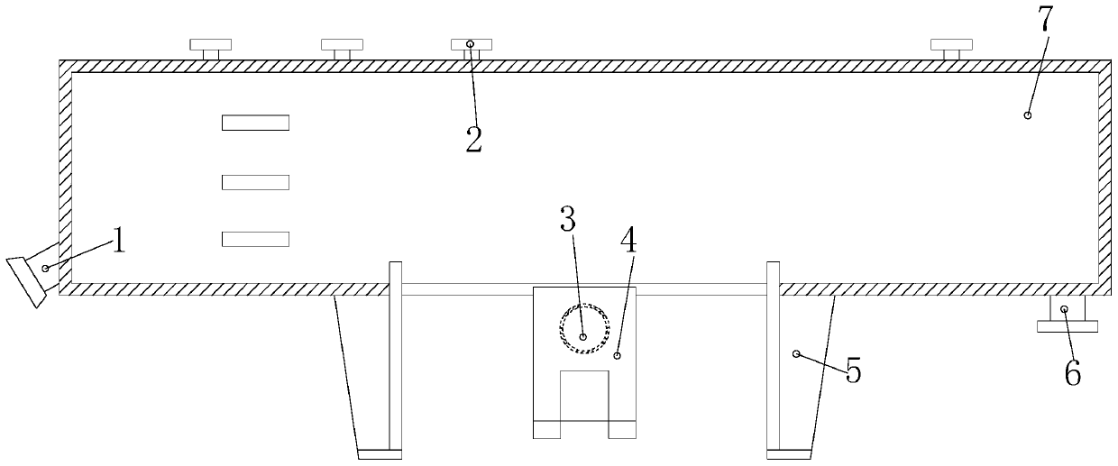
[0022] see Figure 1-Figure 3 , the present invention provides a transformer oil conservator that realizes the replacement of air outlet through rotation. Box 6 and shell 7, the pointer oil gauge 1 and the dirt collection box 6 are respectively installed on the two ends of the shell 7, the pointer oil gauge 1 and the dirt collection box 6 both run through the shell 7, the said The moisture absorber pipe joint 2 is arranged on the top of the casing 7, the gas collecting box 4 is installed in the center of the bottom of the casing 7, and the support feet 5 are provided with two symmetrical structures and arranged on the bottom of the casing 7. The support feet 5 is mechanically welded with the shell 7, and the gas collecting box 4 is provided with an oil conservator air outlet 3, and the oil conservator air outlet 3 communicates with the inner cavity of the shell 7.

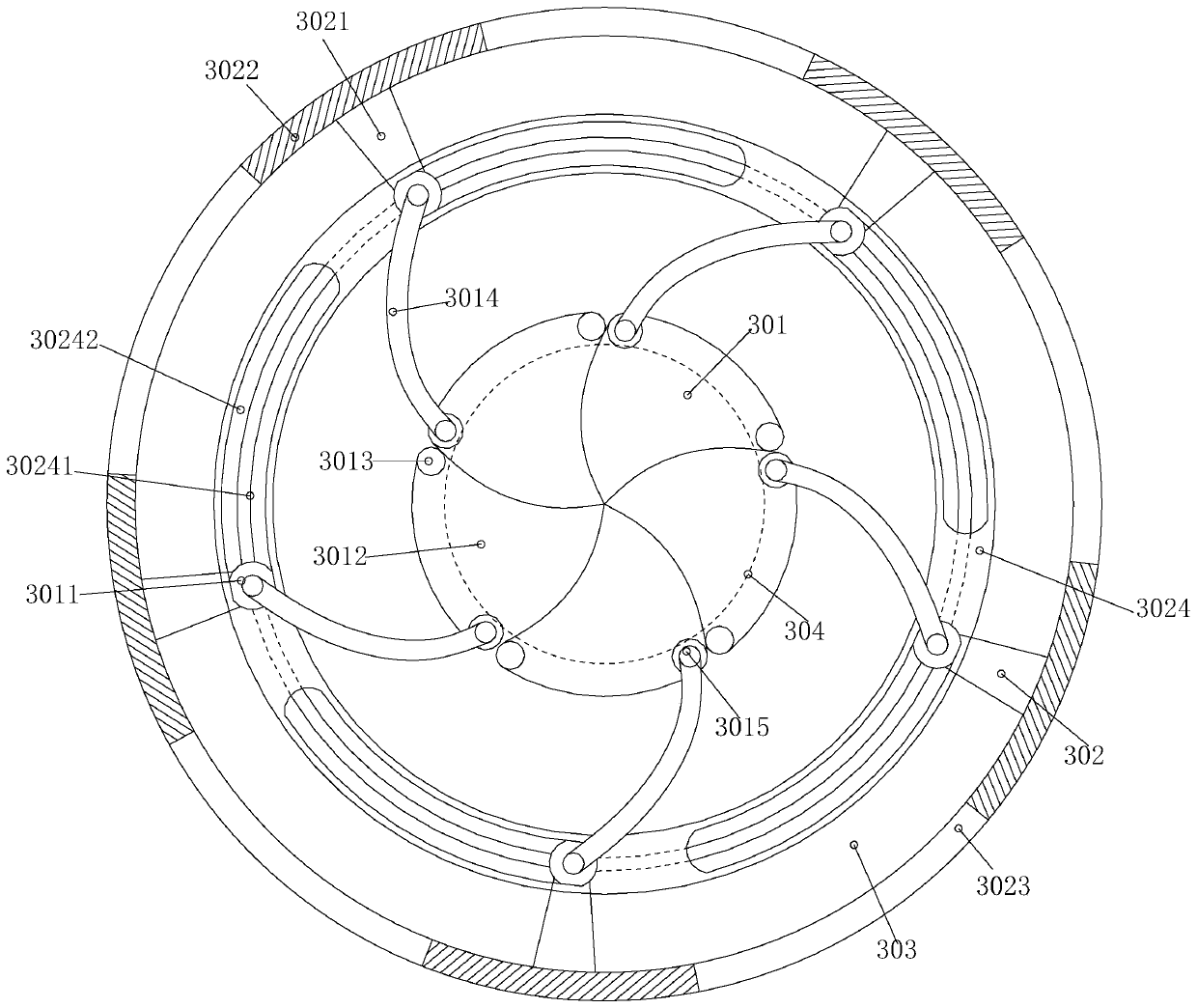
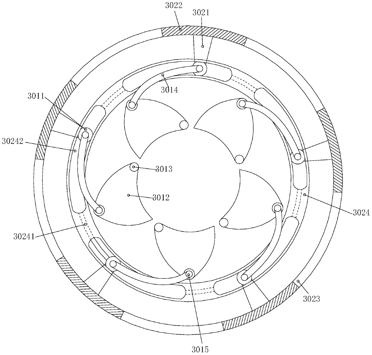
[0023] The air outlet hole 3 of the oil conservator is composed of a resistance mechanism 301, a driving mechan...


PUM


Abstract

The invention discloses a transformer oil pillow realizing replacement of vent hole resistance through rotation. The structure thereof comprises a pointer type oil meter, a moisture absorber pipe joint, an oil pillow air outlet, a gas collecting box, a supporting pin, a dirt collecting box and a casing, wherein the pointer type oil meter and the dirt collecting box are respectively installed on both ends of the casing, and the pointer type oil meter and the dirt collecting box respectively penetrate through the casing. The invention has the beneficial effects that the outer ring layer is rotated clockwise to make the driving connecting rod pull one ends of the shutters connected thereto to rotate clockwise around the fixed rotating shaft, five shutters are separated and expose out of the porous channel so that the cooling oil in the oil pillow can be observed, and the outer ring layer is rotated counterclockwise when the porous channel needs to be closed such that the five shutters areengaged to cover the porous channel to realize the closing of the porous channel, thereby avoiding the cooling oil in the oil pillow from being oxidized and deteriorated due to communication with theoutside air.

Description

technical field [0001] The invention relates to the field of transformer cooling oil protection, in particular to a transformer oil conservator that realizes the replacement of air outlet through resistance through rotation. Background technique [0002] Due to thermal expansion and contraction, the cooling oil in the transformer will flow back and forth between the transformer and the oil conservator, so that the reciprocating flow will also flow the cooling oil in the oil conservator that has deteriorated due to oxidation into the transformer, resulting in the cooling of the transformer cooling oil. The effect becomes worse, and the current transformer cooling oil protection device has the following defects: [0003] In order to facilitate the observation of the volume change of the cooling oil in the oil conservator, an air outlet is directly opened on the transformer oil conservator. Since the air outlet communicates with the air, the cooling oil in the oil conservator d...

Claims


Application Information

Patent Timeline
IPC IPC(8): H01F27/14
Inventor 陈益丹
Owner 临沂文一诺知识产权运营有限公司
Features
  • Generate Ideas
  • Intellectual Property
  • Life Sciences
  • Materials
  • Tech Scout
  • Unparalleled Data Quality
  • Higher Quality Content
  • 60% Fewer Hallucinations
Learn More