

Electric vehicle storage battery charging device
A charging device and electric vehicle technology, applied in the direction of AC network load balancing, etc., can solve the problems of lack of automatic adjustment working mode, increased pressure and difficulty of power grid dispatching, and small power grid support, so as to reduce the peak-to-valley difference and ensure economic benefits , the effect of reducing demand
- Summary
- Abstract
- Description
- Claims
- Application Information
AI Technical Summary
Problems solved by technology
Method used
Image

Examples
Embodiment 1
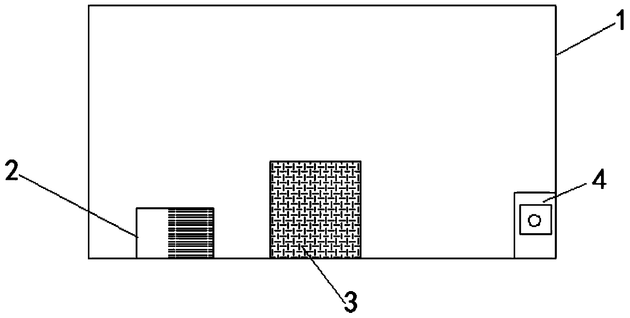
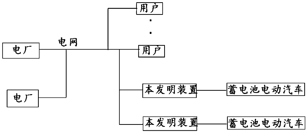
[0019] Embodiment 1: A kind of electric vehicle storage battery charging device provided by the present invention, refer to figure 1 As shown, it includes a housing 1, an AC / DC converter 2 connected to the grid power supply line is fixed inside the housing, a controller 3 connected to the AC / DC converter signal, and a detection chip 4 connected to the controller signal, The detection chip is used to detect the grid frequency, battery power, battery temperature, and charge / discharge current value. The detection chip of the present invention can use the CS6463A metering chip to detect the grid frequency, and the controller can use the ADAM-3900 model sold on the market. When using the charging device of the present invention, refer to figure 2 As shown, one end of the device is connected to the grid power supply side, and the other end is electrically connected to the storage battery. The detection chip on the grid power supply line is used to detect the grid frequency, which ...
Embodiment 2
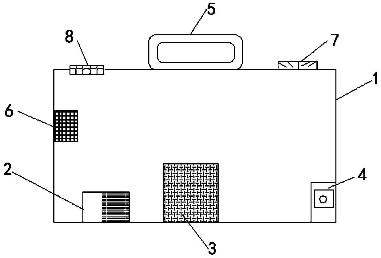
[0020] Embodiment 2: In addition to the structure disclosed in Embodiment 1, in order to further optimize the present invention, refer to image 3 As shown, a control panel 5 for signal transmission with the controller is installed on the outer surface of the housing. A wireless communication chip 6 connected with the controller is also installed inside the casing. The wireless communication chip includes wifi, GPRS, bluetooth, zigbee and other chips with wireless transmission functions, and a bidirectional metering electric meter 7 is also installed on the housing, and the bidirectional metering electric meter is electrically connected with the AC / DC converter, and is connected with the control signal transmission. There are also heat dissipation holes 8 on the outer surface of the housing. The control panel can be KP700 sold on the market, and the two-way meter can be DTSF1352.
[0021] Through the set control panel, you can set the working mode of the device, the thresho...
PUM
 Abstract
Description
Claims
Application Information