
Heading composite die and manufacturing method of heading piece

A composite mold and upsetting technology is applied in the field of forming parts, which can solve the problems of the difficulty of deep processing of the female mold cavity, the inability to form a slender rod, and the difficulty of forming the upsetting head, so as to solve the problem of complex structure forming and strain defects. Easy to eliminate and improve the effect of rod bending problem

Active Publication Date: 2019-05-21
AECC AVIATION POWER CO LTD
View PDF8 Cites 0 Cited by
  • Summary
  • Abstract
  • Description
  • Claims
  • Application Information

AI Technical Summary

Problems solved by technology

[0002] Aeroengine precision forging blade blanks are mostly made of extruded rods and headings. The mold tenons of the headings have deep cavity and complex structure, and the forming of the headings is difficult.
The traditional method of extrusion molding in the female mold has the following disadvantages: 1) The deep processing of the female mold cavity is difficult, and it is difficult to eliminate the strain defects in the cavity during use; 2) During the production process, affected by the parting surface, The head cannot be accurately formed, which affects the forging quality of the subsequent process; 3) The defects of the blank are not easy to repair, and the life of the mold is low; 4) It is impossible to form a slender rod, and often there are defects that the edges and corners of the heading parts are not filled. The bending is serious; 5) Large reverse burrs are generated, and the material utilization rate is only 60%; 6) The installation direction of the upper mold and the lower mold is wrong; the traditional design is only suitable for the area of ​​the cross-section of the cavity along the depth direction. reduced parts

Method used


Image

  • Heading composite die and manufacturing method of heading piece
  • Heading composite die and manufacturing method of heading piece
  • Heading composite die and manufacturing method of heading piece

Examples


Embodiment Construction

[0030] The present invention will be described in detail below in conjunction with the accompanying drawings and specific embodiments.

[0031] In describing the present invention, it should be understood that the terms "center", "longitudinal", "transverse", "upper", "lower", "front", "rear", "left", "right", " The orientations or positional relationships indicated by "vertical", "horizontal", "top", "bottom", "inner" and "outer" are based on the orientations or positional relationships shown in the drawings, and are only for the convenience of describing the present invention and Simplified descriptions, rather than indicating or implying that the device or element referred to must have a particular orientation, be constructed and operate in a particular orientation, and thus should not be construed as limiting the invention. In addition, the terms "first" and "second" are used for descriptive purposes only, and cannot be interpreted as indicating or implying relative import...


PUM


Abstract

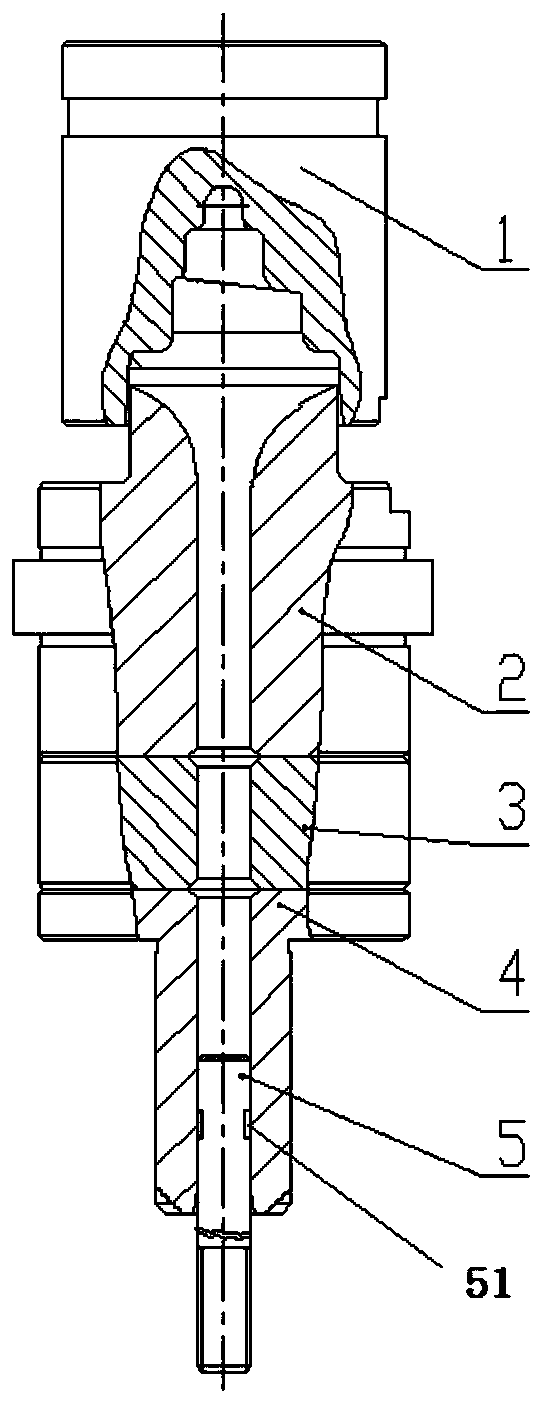
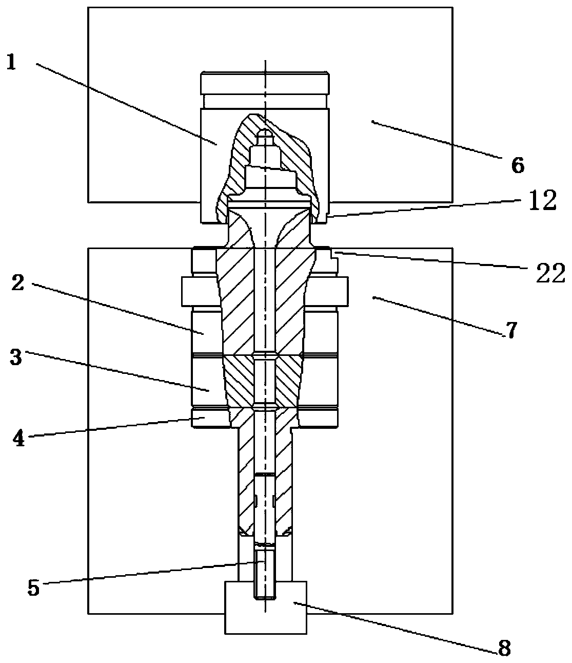
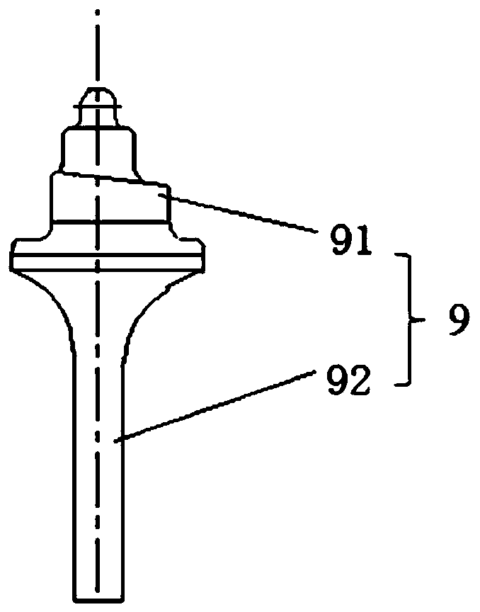
The invention discloses a heading composite die and a manufacturing method of a heading piece. The heading composite die comprises an ejector pin as well as an upper die, a lower die, a cushion blockand a guiding block which are sequentially arranged from top to bottom; an upper die cavity is formed in the upper die; a lower die cavity and a forming hole are formed in the lower die; an ejecting hole is formed in the cushion block; a guiding hole is formed in the guiding block; the forming hole, the guiding hole and the ejecting hole are formed coaxially; the upper die is fixed inside an upperdie seat; the lower die, the cushion block and the guiding block are mounted in a working hole of a lower die seat; the upper part of the ejector pin is located in the guiding hole in the guiding block; and an ejecting switching seat for jacking up or pulling down the ejector pin is arranged at the lower part of the lower die seat. The upper die and the lower die adopt the split design, so that compared with the shape of an originally-designed heading piece, the heading composite die has the advantages that mold stripping and filling are easier, reverse burrs are small and strain defects inside the cavity are easy to eliminate. According to the heading composite die and the manufacturing method, the problem of complex forming of the head structure of the heading piece is solved, and the problem of bending of the rod part during ejection is improved. The material utilization rate is increased through the closed design.

Description

technical field [0001] The invention belongs to the technical field of parts forming, and in particular relates to a heading composite mold and a method for manufacturing a heading piece. Background technique [0002] The precision forging blades of aero-engines are mostly made of extruded rods and headings. The mold tenons of the headings have deep cavity and complex structure, and the forming of the headings is difficult. The traditional method of extrusion molding in the female mold has the following disadvantages: 1) The deep processing of the female mold cavity is difficult, and it is difficult to eliminate the strain defects in the cavity during use; 2) During the production process, affected by the parting surface, The head cannot be accurately formed, which affects the forging quality of the subsequent process; 3) The defects of the blank are not easy to repair, and the life of the mold is low; 4) It is impossible to form a slender rod, and often there are defects th...

Claims


Application Information

Patent Timeline
Patent Type & Authority Applications(China)
IPC IPC(8): B21K3/04B21J13/02B21J13/14
Inventor 宋占利李浩放姚文广赵旭李根宪王昊许岗建苏衍双
Owner AECC AVIATION POWER CO LTD
Learn More