
A pull rope fastening device for internally suspending the holding pole when the transmission iron tower is erected

A technology for transmission iron towers and fastening devices, which is applied in the field of pull rope fastening devices for suspended poles when the transmission iron towers are erected, can solve problems such as damage to the galvanized layer of tower materials, hidden safety hazards, time-consuming and labor-intensive problems, and save manpower and Time, increase the use of safety, ensure the effect of reliability

Active Publication Date: 2021-07-13
国网山东省电力公司建设公司 +2
View PDF0 Cites 0 Cited by
  • Summary
  • Abstract
  • Description
  • Claims
  • Application Information

AI Technical Summary

Problems solved by technology

[0002] In the construction process of power transmission line tower assembly, the inner suspension pole needs to be evenly connected with the main material of the tower leg through the pull rope. Currently, the pull rope is directly tied to the main material of the tower leg. This method exists Some problems: 1. Bind the tail end of the pull rope directly to the main material of the tower leg. It is necessary to line the tower with soft objects to prevent the pull of the pull rope from damaging the main material. If the protection is not in place, the pull rope will be damaged. Destroying the galvanized layer of the tower material; 2. Through the rope winding method, if the winding is not careful, the winding point may move up and down, which brings certain safety hazards; 3. This kind of rope winding method is not easy to operate, time-consuming and laborious

Method used


Image

  • A pull rope fastening device for internally suspending the holding pole when the transmission iron tower is erected
  • A pull rope fastening device for internally suspending the holding pole when the transmission iron tower is erected
  • A pull rope fastening device for internally suspending the holding pole when the transmission iron tower is erected

Examples


Embodiment 1

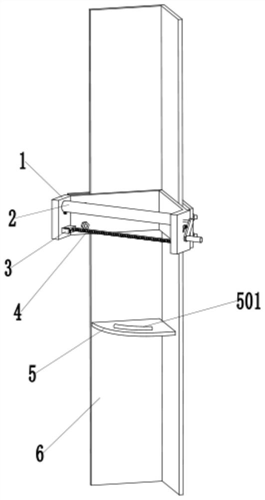
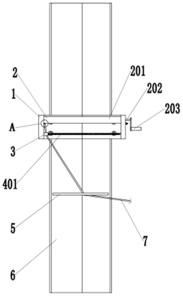
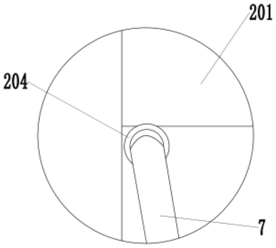
[0035] Such as figure 1 , 2 As shown in , 4, a stay rope fastening device for suspending the pole when the transmission iron tower is erected includes a clamping device 1 and a rope winding device 2, and the clamping device 1 includes an outer angle steel plate 101 and an inner angle steel plate 102. The end of the outer angle steel plate 101 and the end of the inner angle steel plate 102 are connected by bolts. One end of the inner angle steel plate 102 is provided with a first connection box 103, and the other end of the inner angle steel plate 102 is provided with a second connection box 104. The device 2 includes a rope winding drum 201, a rotating shaft 202, and a handle 203. The rope winding drum 201 is set on the outside of the rotating shaft 202. The rope winding drum 201 is arranged between the first connection box 103 and the second connection box 104. The rotating shaft 202 One end of the connecting box 103 is connected to the first connecting box 103, and the hand...

Embodiment 2

[0040] In order to ensure that the stay rope 7 can be evenly wound on the rope winding drum 201, to prevent local winding only, or the stay rope 7 is inclined to cause inconvenient winding.

[0041] Such as figure 1 , 2 As shown, a guide rail 4 is provided below the rope winding drum 201, and the guide rail 4 is connected to the rotating shaft 202, and a wire slider 3 is provided on the guide rail 4. Through the wire slider 3, the stay rope can be evenly wound on the rope winding drum 201, preventing excessive local winding of the rope, saving space, making the rope winding drum 201 more evenly stressed, and improving the bearing capacity.

[0042] Such as figure 2 , 4 As shown, the guide rail 4 includes a lead screw 401 and a slide bar 402, and the slide bar 402 is arranged in parallel with the lead screw 401, as Figure 7 As shown, the first connection box 103 is provided with driving teeth 106, driving teeth 107, and driven teeth 108, and the two ends of the sliding ro...

Embodiment 3

[0047] In order to prevent the wire slider 3 from being damaged at a certain angle between the stay rope 7 and the wire slider 3 during the rope winding process, it is not conducive to rope winding.

[0048] Such as figure 1 As shown, in order to solve the above problems, a guide plate 5 is also provided in this embodiment, the guide plate 5 is arranged below the guide rail 4, the guide plate 5 is welded to the main material 6 of the tower leg, and the guide plate 4 is provided with Guide hole 501.

[0049] The edge of the guide hole 501 is rounded, and the guide hole 501 is an arc hole. On the one hand, the guide plate 5 plays the role of reinforcing the main material 6 of the tower leg; on the other hand, an arc-shaped guide hole 501 is provided on the guide plate 5, and the guide hole 501 can guide the stay rope 7 to prevent the stay rope 7 from shifting. , to prevent the wire slider 3 from being directly pulled by the pull rope 7 to prevent damage to the wire slider 3, a...


PUM


Abstract

The invention discloses a pull rope fastening device for internally suspending a pole when a power transmission tower is erected, which includes a clamping device and a rope winding device, the clamping device includes an outer angle steel plate and an inner angle steel plate, and the end of the outer angle steel plate The ends of the inner angle steel plates are connected by bolts, one end of the inner angle steel plates is provided with a first connection box, the other end of the inner angle steel plates is provided with a second connection box, and the rope winding device includes a rope winding drum, a rotating shaft, and a handle. The rope winding cylinder is set on the outside of the rotating shaft, the rope winding cylinder is arranged between the first connecting box and the second connecting box, one end of the rotating shaft is connected with the first connecting box, and the turning handle is arranged on the outside of the second connecting box, The second connection box is provided with a ratchet and a pawl, the ratchet is sleeved on the rotating shaft, the pawl cooperates with the ratchet, and one end of the ratchet is connected with the inner wall of the second connection box through the rotation shaft.

Description

technical field [0001] The invention relates to the technical field of fastening devices for pull ropes when power transmission iron towers are erected, in particular to a pull rope fastening device for internally suspending holding poles when electric power transmission towers are erected. Background technique [0002] In the construction process of power transmission line tower assembly, the inner suspension pole needs to be evenly connected with the main material of the tower leg through the pull rope. Currently, the pull rope is directly tied to the main material of the tower leg. This method exists Some problems: 1. Bind the tail end of the pull rope directly to the main material of the tower leg. It is necessary to line the tower with soft objects to prevent the pull of the pull rope from damaging the main material. If the protection is not in place, the pull rope will be damaged. Destroying the galvanized layer of the tower material; 2. Through the rope winding method...

Claims


Application Information

Patent Timeline
Patent Type & Authority Patents(China)
IPC IPC(8): E04H12/34
Inventor 李睿高兴强张洪建娄凤强张福友王晓燕王佳科孙祚能汤晓先伦崔巍葛平富
Owner 国网山东省电力公司建设公司
Learn More