
Center slewing connection structure and crane

A connection structure and rotary body technology, applied in the direction of cranes, connections, rotary collectors, etc., can solve the problems of limited space between the luffing cylinder and the turntable, the infeasibility of the installation method of the center rotation, and more space for the car, so as to avoid the Water may be disturbed, easy to arrange, disassemble and maintain, and avoid occupying too much space

Active Publication Date: 2017-12-19
SANY AUTOMOBILE HOISTING MACHINERY
View PDF1 Cites 0 Cited by
  • Summary
  • Abstract
  • Description
  • Claims
  • Application Information

AI Technical Summary

Problems solved by technology

[0003] A common central rotary joint is generally composed of a shell, a body core, a seal, and ancillary devices. A connected annular oil passage, and an oil port connected to the oil passage is provided on the shell. At present, when the central rotary joint is used for a truck crane, a mounting hole is usually opened on the turntable, and the central rotary joint is placed in the mounting hole. , connect the top of the body core of the central rotary joint with the bolts of the mounting plate and the turntable around the mounting hole, and connect the shell of the central rotary joint with the frame through a non-supporting detachable structural member; in order to meet the stability of the installation, The mounting plate between the top of the body core and the turntable is usually relatively large, occupying at least the general space of the mounting hole, which will affect the installation efficiency of the oil port below the mounting plate, such as the oil port at a higher position on the shell, and the oil pipe of the frame; in addition, due to the There is an opening under the frame, usually from this opening to realize the installation of the oil port and the oil pipe at the lower position on the housing or the assembly between the housing and the frame
[0004] In traditional truck cranes, using the aforementioned center swivel joint installation method will not cause great impact, and although the installation speed is slow, it is also within an acceptable range
However, in order to meet the needs of customers and to better adapt to the needs of use, recently, in order to continuously improve the performance of truck cranes or make the structure of truck cranes more compact, the applicant of this application has invested a lot of manpower and material resources. During the process, the inventor of the present application found that: in the original method, the hinged position of the bottom end of the luffing cylinder, the aforementioned central rotary joint should be arranged on the turntable of the truck crane from front to back (with the forward direction of the truck crane in normal driving as the front). The installation position and the hinge position of the basic arm tail, the installation method of the aforementioned center swivel joint needs to occupy more space on the turntable, but if the truck crane is improved, the space between the aforementioned two hinge positions is small or insufficient , or after the improvement of the truck crane, the space between the luffing cylinder and the turntable is extremely limited because the installation position of the center rotary joint is set before the hinge position at the bottom end of the luffing cylinder (because the luffing cylinder is roughly horizontal before luffing). When the truck crane is placed above the turntable), the aforementioned center rotation installation method is difficult to adopt, not only difficult to install, but also difficult to maintain; on this basis, if the truck crane is improved, it is necessary to install other devices at the opening below the frame so that the opening is no longer When passing freely, the aforementioned center-turning installation method will be even more unfeasible

Method used


Image

  • Center slewing connection structure and crane
  • Center slewing connection structure and crane

Examples


Embodiment Construction

[0052] It should be pointed out that the description and sequence of specific structures in this section are only descriptions of specific embodiments, and should not be considered as limiting the protection scope of the present invention. In addition, the embodiments in this section and the features in the embodiments can be combined with each other under the condition of no conflict.

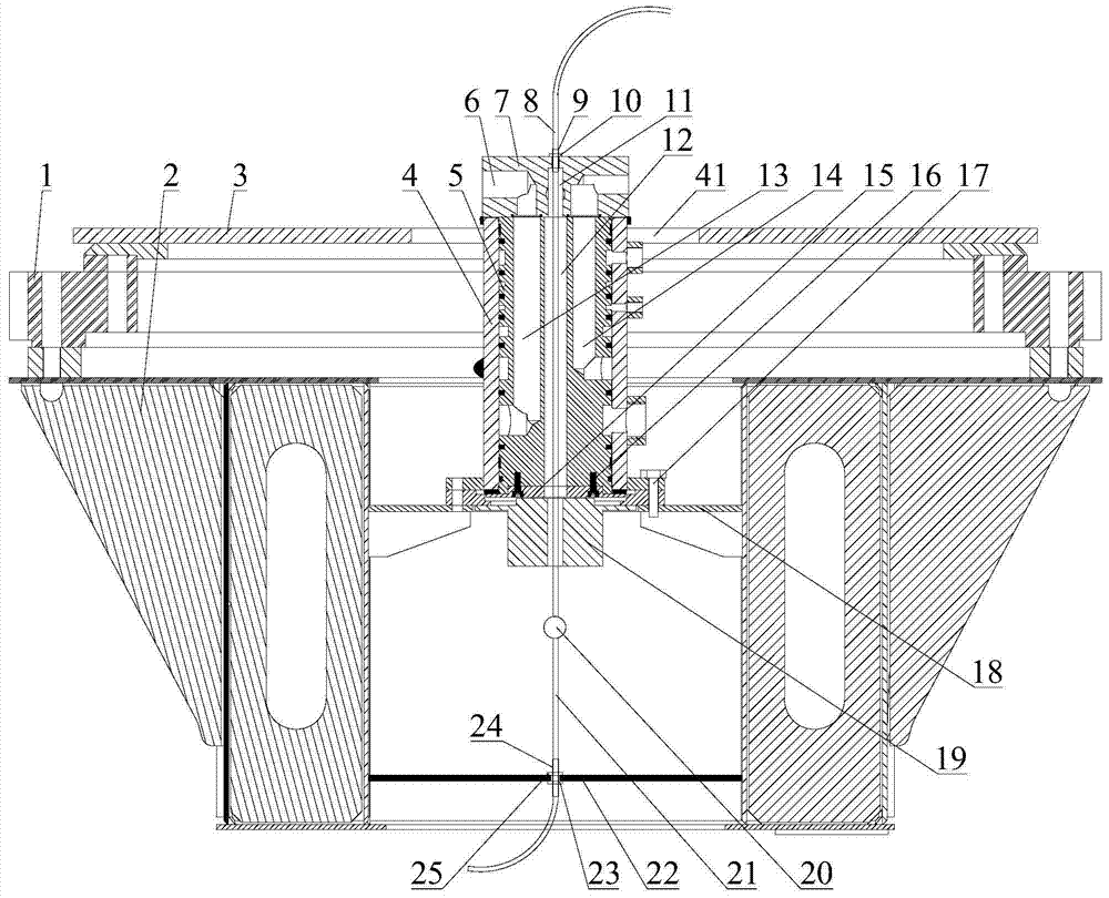
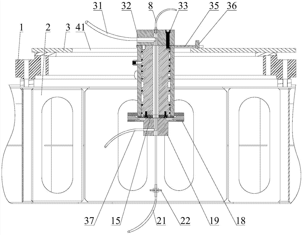
[0053] Please also refer to figure 1 with figure 2 , the central rotary connection structure of the embodiment of the present invention will be described in detail below in conjunction with the accompanying drawings.

[0054] As shown in the figure, the central rotary connection structure of this embodiment may include a vehicle frame 2, a turntable 3, a rotary body, a boarding wire 31, a boarding wire 37, a conductive ring 19, a boarding cable 8 and a boarding cable 21.

[0055] Wherein, the turntable 3 is rotatably arranged above the vehicle frame 2. In practice, the turntable 3 can be co...


PUM


Abstract

The invention discloses a center rotation connecting structure and a crane. The center rotation connecting structure comprises a vehicle frame, a rotating table and a rotary body, wherein a mounting hole is formed in the rotating table; the rotary body is positioned in the mounting hole. The center rotation connecting structure is characterized in that the rotary body comprises a shell, a body core and an upper cover body, wherein the body core can be rotationally arranged in the shell; the upper cover body is arranged on the top part of the body core and is fixedly connected with a shifting fork; a shifting fork rod is fixedly connected to the rotating table; the shifting fork is matched with the shifting fork rod; a supporting base is arranged on the vehicle frame; the lower part of the shell is fixedly arranged on the supporting base. The center rotation connecting structure can be applied to an improved auto crane, so that the occupation space on the rotating table can be effectively reduced, and the difficulty of arrangement and maintenance is effectively reduced.

Description

technical field [0001] The invention relates to the technical field of center slewing, in particular to a center slewing connection structure and a crane. Background technique [0002] The central rotary joint or central rotary body is a device for construction machinery such as truck cranes to realize the connection between getting on and off the car. Through the central rotary joint, the hydraulic and electrical transmission of the getting off the car can not be affected by the free rotation of the getting on and off the car, and the hydraulic oil and electrical signals are stable and reliable. The ground is transmitted to the boarding car to realize the linkage control of getting on and off the car. [0003] A common central rotary joint is generally composed of a shell, a body core, a seal, and ancillary devices. A connected annular oil passage, and an oil port connected to the oil passage is provided on the shell. At present, when the central rotary joint is used for a...

Claims


Application Information

Patent Timeline
Patent Type & Authority Patents(China)
IPC IPC(8): F16L39/06H01R39/64B66C23/84
CPCB66C23/84F16L39/06H01R39/64
Inventor 饶文武谭磊任利有
Owner SANY AUTOMOBILE HOISTING MACHINERY
Learn More