Debugging bracket and method for infrared laser emitting head

A technology of infrared laser and debugging method, which is applied in the direction of mechanical equipment, connecting components, etc., can solve the problems of human injury, inconvenient operation of infrared laser emitting head, and increase the scrapping rate of infrared laser emitting head, and achieve high debugging accuracy and easy operation Effect

Pending Publication Date: 2019-05-21
SHENZHEN KELU INTERNET OF THINGS INFORMATION TECH CO LTD
View PDF0 Cites 0 Cited by
  • Summary
  • Abstract
  • Description
  • Claims
  • Application Information

AI Technical Summary

Problems solved by technology

[0005] The first method is to use screws to fix and position the laser tube from four directions, which causes inconvenience in operation and cannot remove the screws after the adjustment is completed. The laser transmitter head cannot be used in some occasions
In the second method, because the UV glue needs to be solidified quickly under the irradiation of ultraviolet light, the operator will be exposed to ultraviolet light during the debugging process, which will cause damage to the human body and cannot be reworked once the operation error occurs during the curing of the UV glue. , increasing the scrap rate of infrared laser emitters

Method used


Image

  • Debugging bracket and method for infrared laser emitting head
  • Debugging bracket and method for infrared laser emitting head
  • Debugging bracket and method for infrared laser emitting head

Examples


Embodiment Construction

[0041] It should be noted that the embodiments in this application and the features in the embodiments can be combined with each other if there is no conflict.

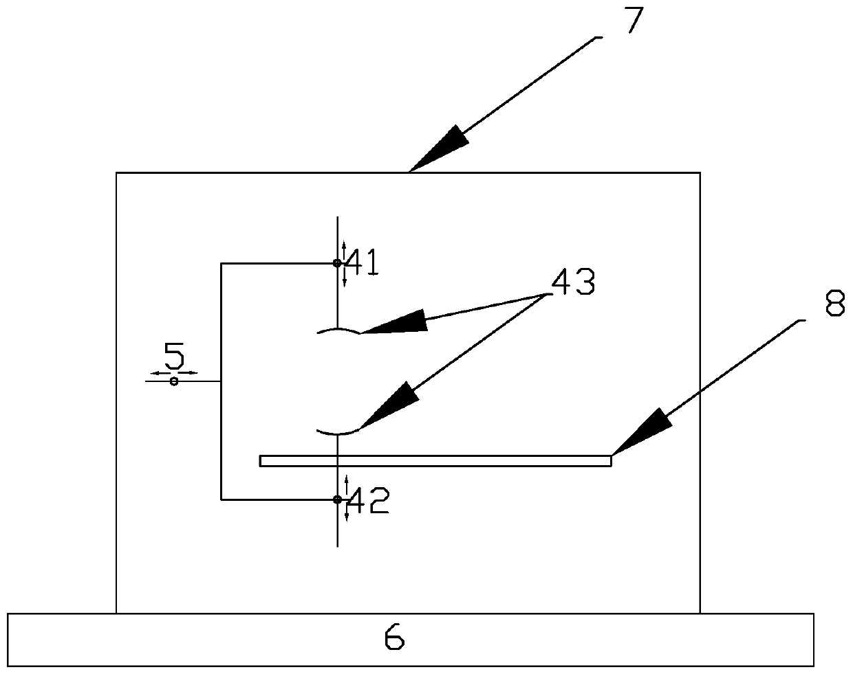
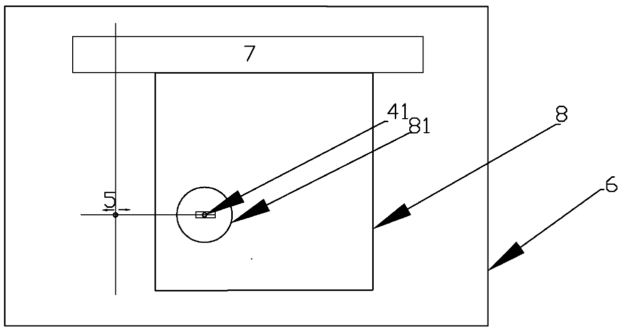
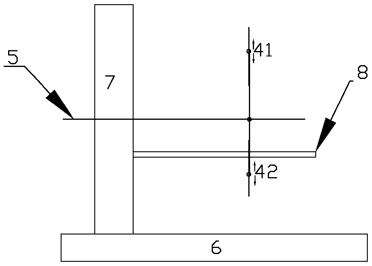
[0042] Such as figure 1 As shown, an infrared laser emitting head debugging support in the present invention includes: a base 6, a vertical support 7, a carrying support 8, a probe support 5, a first debugging probe 41 and a second debugging probe 42; , The vertical support 7 is vertically fixed above the base 6, the load support 8 is fixed on the vertical support 7, and the load support 8 is parallel to the base 6, the probe support 5 is fixed on the vertical support 7, the first debugging probe 41 Both and the second debugging probe 42 are fixed on the probe holder 5.

[0043] Specifically, refer to Figure 1 to Figure 3 , The end of the first debugging probe 41 and the end of the second debugging probe 41 are both provided with an arc-shaped clamping structure 43, the radii of the two arc-shaped clamping structures 43 a...


PUM


Abstract

The invention discloses a debugging bracket and method for an infrared laser emitting head. The debugging bracket for the infrared laser emitting head comprises a base, a vertical bracket, a carryingbracket, a probe bracket and debugging probes. The position adjustment of a positioning laser tube is carried out in four directions of up, down, left and right by the probe bracket and the probes, and the debugging bracket for the infrared laser emitting head with simple operation and high debugging precision and the efficient and safe debugging method for the infrared laser emitting head are provided.

Description

Technical field [0001] The invention relates to the technical field of infrared laser emitting head debugging, in particular to a debugging bracket and a debugging method of an infrared laser emitting head. Background technique [0002] With the continuous development of infrared laser technology, infrared laser technology is widely used in various fields. In the prior art, the debugging of the infrared laser emitting head generally adopts the following two methods: [0003] 1. Fix the position of the infrared laser tube, use screws to adjust and fix the laser tube in four directions. [0004] 2. Fix the position of the infrared laser tube, use UV glue to fix the positioning laser tube, and irradiate the UV glue with ultraviolet light, adjust the position of the positioning laser tube during the curing process of the UV glue. [0005] The first method uses screws to fix and position the laser tube from four directions, which causes inconvenience in operation and the inability to remo...

Claims


Application Information

Patent Timeline
IPC IPC(8): F16B11/00
Inventor 郝懿
Owner SHENZHEN KELU INTERNET OF THINGS INFORMATION TECH CO LTD
Why Eureka
Try Eureka