Equipment support leg

A technology of equipment and feet, applied in the field of supporting components, can solve the problems of non-adjustable height of the bracket, inconvenient use, uneven ground, etc., and achieve the effect of reducing workload, fast height, and height adjustment

Inactive Publication Date: 2019-05-21
YANGZHOU HENGDE IND TECH CO LTD
View PDF0 Cites 0 Cited by
  • Summary
  • Abstract
  • Description
  • Claims
  • Application Information

AI Technical Summary

Problems solved by technology

[0003] There are many kinds of supporting feet used for equipment in the prior art, such as those directly fixed on the equipment by fixing bolts, or installed on the equipment by welding. It is impossible to adjust the distance between the feet and the equipment. Sometimes the ground may not be flat during use. At this time, the height of the bracket cannot be adjusted when placing the equipment, causing the equipment to shake easily during use and inconvenient to use. And shorten the service life of the equipment
Later, height-adjustable feet appeared, but the installation of the feet needs to be installed first, then put the equipment upright, and observe its levelness. If it is not level, you need to turn the equipment over and readjust the height of the feet until the equipment is level. Increased workload for foot installation

Method used


Image

  • Equipment support leg
  • Equipment support leg
  • Equipment support leg

Examples


Embodiment approach

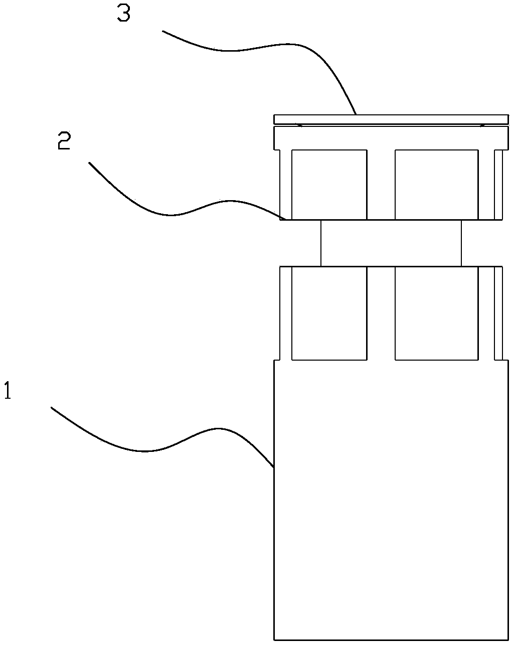
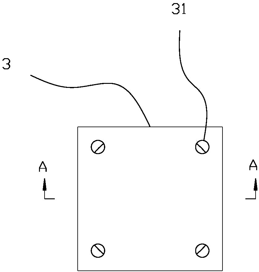
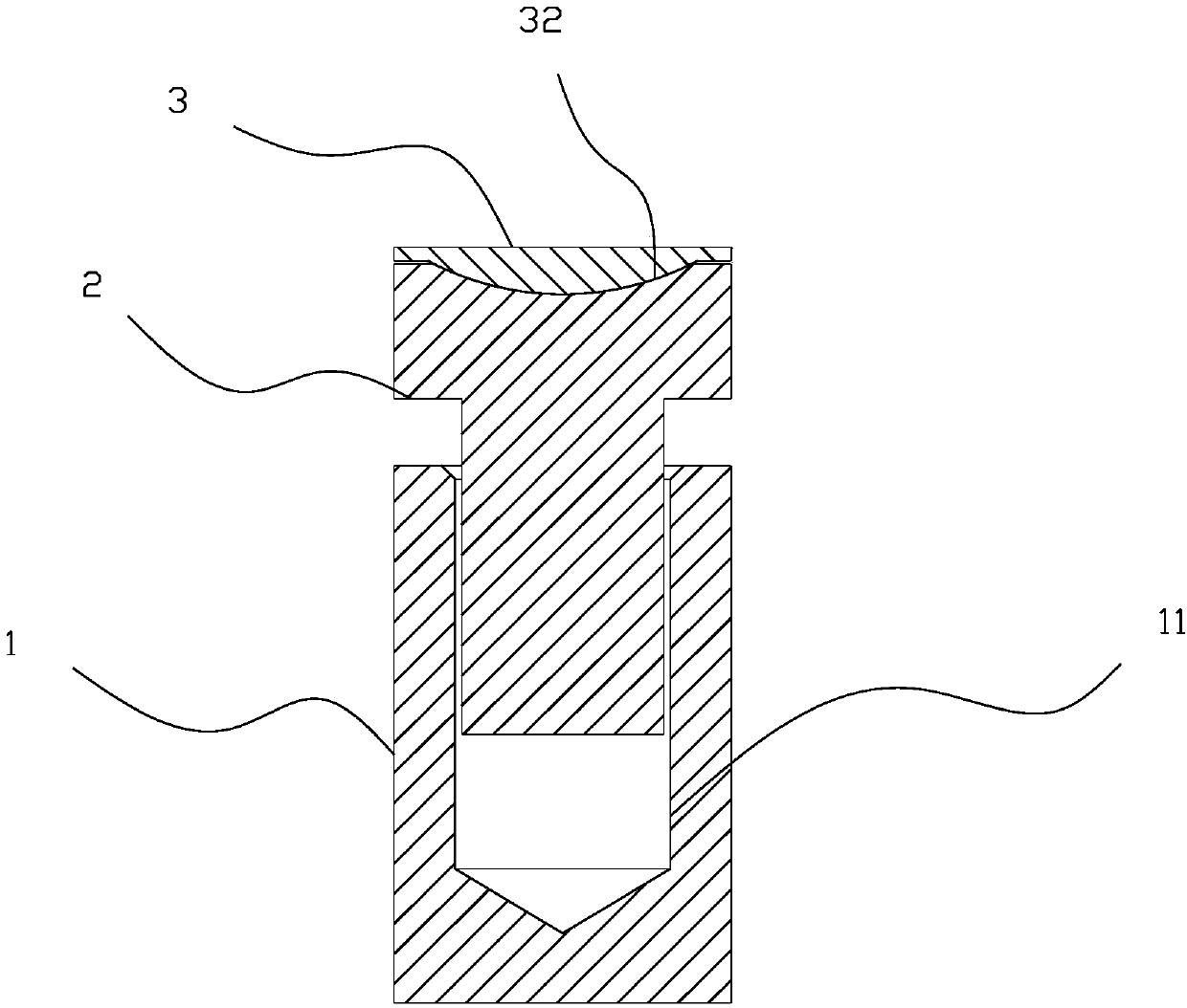
[0023] Figure 1-3 It is the first embodiment of the present invention, the bottom of the adjustment block 2 is a screw, the base 1 is provided with a screw groove 11 for equipment with the screw, and the adjustment block 2 or the base 1 is provided with a wrench to adjust the force noodle. The adjustment of the height of the equipment can be realized by adjusting the adjustment block 2 or the base 1 with a wrench. Because the upper block 3 and the adjustment block are not fixed, no force will be applied to the upper block 3 during the height adjustment process, and there will be no movement. On the device, it saves time and effort to adjust. The arc-shaped protrusion can reduce the frictional force between the upper block 3 and the adjustment block 2, so that the adjustment action is more labor-saving. A spring or an air bag can be installed under the screw rod, which can compensate the force of the overweight equipment and prevent the screw thread from being crushed and fa...


PUM


Abstract

The invention relates to a support module, in particular to equipment support leg; and the equipment support leg is adjustable in height and low in mounting workload. The equipment support leg comprises a base, an adjusting block and an upper block in sequence from bottom to top; the upper block is provided with multiple mounting holes; projections are arranged on the inner sides of the mounting holes and on the bottom surface of the upper block; first grooves matched with the projections are formed in the top surface of the adjusting block; and the height between the base and the adjusting block is adjustable. The bottom of the adjusting block is provided with a screw rod; the base is provided with a thread groove matched with the screw rod; and the adjusting block or the base is providedwith a spanner adjusting exertion surface. A second groove is formed in the base; two symmetrical thread holes are formed in the side wall of the second groove; an adjusting rod penetrating through the two thread holes is arranged in the thread holes; and a cam fixed on the adjusting rod is arranged in the second groove and on the adjusting rod. The equipment support leg is split, and can quicklyadjust the height to reduce the mounting workload.

Description

technical field [0001] The invention relates to a support assembly, in particular to an equipment support foot. Background technique [0002] During the production process, in order to avoid the equipment being damaged by direct contact with the ground, feet are generally provided at the lower end to avoid direct contact with the ground. [0003] There are many kinds of supporting feet used for equipment in the prior art, such as those directly fixed on the equipment by fixing bolts, or installed on the equipment by welding. It is impossible to adjust the distance between the feet and the equipment. Sometimes the ground may not be flat during use. At this time, the height of the bracket cannot be adjusted when placing the equipment, causing the equipment to shake easily during use and inconvenient to use. And shorten the service life of equipment. Later, height-adjustable feet appeared, but the installation of the feet needs to be installed first, then put the equipment up...

Claims


Application Information

Patent Timeline
IPC IPC(8): F16M7/00
Inventor 庄瑞斌宰广平许宝福顾维
Owner YANGZHOU HENGDE IND TECH CO LTD
Why Eureka
Try Eureka