
A Dynamic Target Prediction and Guidance Method for Individual Guided Rockets

A dynamic target and target technology, applied in the direction control system, offensive equipment, weapon accessories, etc., can solve the problems of reducing the accuracy of individual guided rockets, the available maneuvering overload cannot be too large, and the rocket misses the target, etc.

Active Publication Date: 2021-02-09
北京恒星箭翔科技有限公司
View PDF5 Cites 0 Cited by
  • Summary
  • Abstract
  • Description
  • Claims
  • Application Information

AI Technical Summary

Problems solved by technology

However, the traditional guidance law generally uses missiles as the guidance object, which requires the missile to have a large enough maneuvering overload capability to ensure the guidance accuracy. Maneuvering overload is usually impossible to be too large, which may cause the available overload of the rocket to be less than the required overload required by the guidance law. This situation will also cause the rocket to miss the target, greatly reducing the ability to damage the target
[0005] The guidance law of predictive meeting point can greatly reduce the requirements for the overload capability of guided rockets. However, the currently used guidance law of predictive meeting point is calculated before the launch of the target stage rocket. Once the predictive point is set to The system can no longer be adjusted, and due to the influence of factors such as wind, temperature, and engine parameters during the flight of the rocket, there will be time-range dispersion, which will greatly reduce the accuracy of the individual guided rocket

Method used


Image

  • A Dynamic Target Prediction and Guidance Method for Individual Guided Rockets
  • A Dynamic Target Prediction and Guidance Method for Individual Guided Rockets
  • A Dynamic Target Prediction and Guidance Method for Individual Guided Rockets

Examples


Embodiment Construction

[0060] The present invention will be described in detail below with reference to the accompanying drawings and examples.

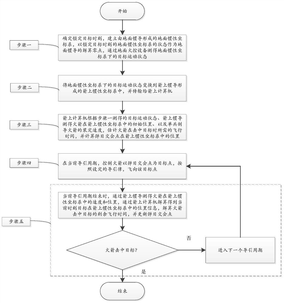
[0061] The invention provides a dynamic target prediction and guidance method for individual guided rockets, the process of which is as follows figure 1 As shown, this method is used to guide the process of the individual guided rocket attacking the target, and the method includes the following steps:

[0062] Step 1. Determine the time to lock the target, establish the ground inertial coordinate system formed by the ground inertial navigation, take the state of the ground inertial coordinate system at the time of locking the target as the zero point of the ground inertial navigation, and measure the ground inertial coordinates through the ground fire control equipment The motion state of the target under the system, including the jerk, acceleration, velocity and position of the target.

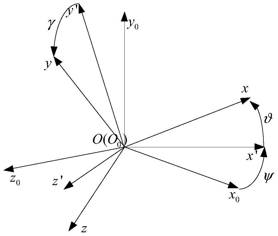
[0063] The ground inertial coordinate system established in the emb...


PUM


Abstract

The invention discloses a single-soldier guided rocket dynamic target prediction and guidance method, which can effectively reduce the normal overload of a rocket in the flight process and ensure therelatively high hit accuracy. The single-soldier guided rocket dynamic target prediction and guidance method comprises the following steps of: measuring the motion state of the target in a ground inertial coordinate system by ground fire control equipment, transforming into the inertial coordinate system of the rocket and transmitting to a computer on the rocket; using the computer on the rocket to estimate the flight time required for the rocket to hit the target and calculating the point of intersection of a guided missile and the target according to the motion state of the target, the initial position of the rocket in the inertial coordinate system of the rocket and the set speed of the single-soldier guided rocket; in the current guidance period, controlling the rocket to fly to the target point according to the set guidance law by taking the point of intersection of the guided missile and the target as the target point; when the current guidance period ends, obtaining the positioninformation of the target in the inertial coordinate system of the rocket by solving with the computer on the rocket, solving the remaining flight time of the rocket hitting the target, and updatingthe point of intersection of the guided missile and the target; and entering the next guidance period, and repeatedly executing till the rocket hits the target.

Description

technical field [0001] The invention relates to the technical field of guided weapon guidance, in particular to a method for predicting and guiding a dynamic target of an individual guided rocket. Background technique [0002] As a traditional individual weapon, individual uncontrolled rockets play an important role in attacking armored vehicles, construction fortifications and low-altitude targets. However, when attacking moving targets, especially those with strong maneuverability, traditional uncontrolled individual rockets have obvious deficiencies in accuracy. [0003] First of all, individual uncontrolled rockets have no guidance and control function. When attacking a moving target, it is necessary to rely on the shooter to estimate the target's motion state. By predicting the intersection point when the rocket hits the target, the rocket is launched at a leading angle to attack the target. This attack method has very high requirements on the shooter's operation, and ...

Claims


Application Information

Patent Timeline
Patent Type & Authority Patents(China)
IPC IPC(8): F41G7/00
Inventor 于剑桥蒋军
Owner 北京恒星箭翔科技有限公司
Learn More