
A Low Profile Vertically Polarized UAV Antenna

A vertical polarization, drone technology, applied in the direction of antenna, antenna grounding device, antenna grounding switch structure connection, etc., can solve the problems of large size and high profile of drone antenna, and achieve radiation performance, vertical polarization radiation Performance, small air resistance effect

Active Publication Date: 2021-03-23
XIDIAN UNIV
View PDF5 Cites 0 Cited by
  • Summary
  • Abstract
  • Description
  • Claims
  • Application Information

AI Technical Summary

Problems solved by technology

[0005] The purpose of the present invention is to overcome the deficiencies of the above-mentioned prior art, and propose a low-profile vertically polarized unmanned aerial vehicle antenna, which is used to solve the technical problems of high profile and large volume of the unmanned aerial vehicle antenna in the prior art

Method used


Image

  • A Low Profile Vertically Polarized UAV Antenna
  • A Low Profile Vertically Polarized UAV Antenna
  • A Low Profile Vertically Polarized UAV Antenna

Examples


Embodiment 1

[0024] refer to figure 1 , figure 2 , image 3 and Figure 4

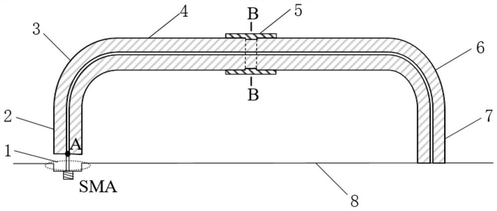
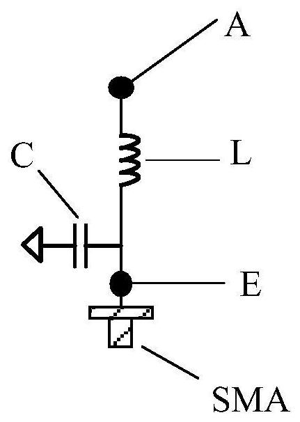
[0025] A low-profile vertically polarized unmanned aerial vehicle antenna, including a matching circuit 1, a feeding radiation coaxial line 2, a first bent coaxial line 3, an inductive loading line 4, a capacitive loading line 5, a second bent coaxial line axis 6, ground radiation coaxial line 7 and metal floor 8; the input end E of the matching circuit 1 is connected to an SMA connector, and the other end is connected to the feed end of the feed radiation coaxial line 2; the feed radiation The inner conductor of the feeding end of the coaxial line 2 is connected to the outer conductor, the other end is connected to one end of the first bent coaxial line 3, and the two ends of the inductive loading line 4 are respectively connected to the first bent coaxial line 3 is connected to one end of the second bent coaxial line 6, the other end of the second bent coaxial line 6 is connected to one end of the grounded r...

Embodiment 2

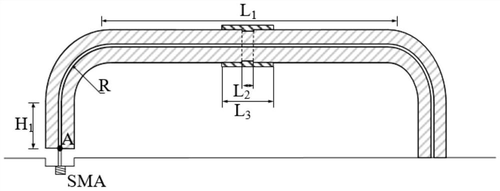
[0032] The inner conductor and the outer conductor of the feeding end of the feeding radiating coaxial line are connected by welding, and the lengths of the feeding radiating coaxial line 2 and the grounding radiating coaxial line 7 are both H 1 , where H 1 11.0mm to 13.0mm. h 1 is 11.0mm.

[0033]The bending radii of the conductors in the first bent coaxial line 3 and the second bent coaxial line 6 are both R, wherein R is 9.0mm˜11.0mm. R is 9.0mm.

[0034] The length of the inductive loading line 4 is L 1 , where L 1 is 78.0mm to 82.0mm, and the length of the disconnection of the outer conductor at the center position of the inductive loading line 4 is L 2 , where L 2 2.0mm to 4.0mm. L 1 78.0mm, L 2 2.0mm.

[0035] The length of the capacitive loading line 5 is L 3 , where L 3 The distance between the capacitive loading line 5 and the inductive loading line 4 is D, wherein D is 0.1mm-0.3mm. L 3 is 8.0mm and D is 0.1mm.

Embodiment 3

[0037] The inner conductor and the outer conductor of the feeding end of the feeding radiating coaxial line are connected by welding, and the lengths of the feeding radiating coaxial line 2 and the grounding radiating coaxial line 7 are both H 1 , where H 1 11.0mm to 13.0mm. h 1 is 13.0mm.

[0038] The bending radii of the conductors in the first bent coaxial line 3 and the second bent coaxial line 6 are both R, wherein R is 9.0mm˜11.0mm. R is 11.0mm.

[0039] The length of the inductive loading line 4 is L 1 , where L 1 is 78.0mm to 82.0mm, and the length of the disconnection of the outer conductor at the center position of the inductive loading line 4 is L 2 , where L 2 2.0mm to 4.0mm. L 1 82.0mm, L 2 is 4.0mm.

[0040] The length of the capacitive loading line 5 is L 3 , where L 3 The distance between the capacitive loading line 5 and the inductive loading line 4 is D, wherein D is 0.1mm-0.3mm. L 3 is 12.0mm and D is 0.3mm.


PUM


Abstract

The invention relates to a low-section vertical polarization unmanned aerial vehicle antenna. The low-section vertical polarization unmanned aerial vehicle antenna comprises a matching circuit, a feedradiation coaxial line, a first bending coaxial line, an inductive load line, a capacitive load line, a second bending coaxial line, a grounding radiation coaxial line and a metal floor; an inner conductor of a feed end of the feed radiation coaxial line is connected with an outer conductor, and the other end is connected with one end of the first bending coaxial line; two ends of the inductive load line are connected with one end of each of the first bending coaxial line and the second bending coaxial line; the other end of the second bending coaxial line is connected with one end of the grounding radiation coaxial line, the inner conductor of the other end of the grounding radiation coaxial line and the outer conductor are connected with the metal floor; and the capacitive load line isarranged at a center symmetric location of the inductive load line. The antenna disclosed by the invention belongs to a wire antenna, the structure weight is light, and the air resistance is small; the unmanned aerial vehicle antenna has a directional diaphragm similar to the monopole antenna, and the technical problem that the unmanned aerial vehicle antenna is high in section and large in volumein the prior art is solved.

Description

technical field [0001] The invention belongs to the technical field of antennas, and in particular relates to a low-profile vertically polarized unmanned aerial vehicle antenna, which can be used for transmitting and receiving unmanned aerial vehicle signals. Background technique [0002] In recent years, with the rapid development of UAV technology, the application of UAV has set off a research boom in this field worldwide, such as in environmental monitoring, agricultural plant protection, aerial photography, etc. UAVs usually need to communicate wirelessly with the ground controller. Therefore, the UAV antenna should have a horizontal omnidirectional radiation pattern and vertical polarization, which can ensure that the UAV can receive signals from any direction of the ground controller. The antennas commonly used in UAV communication systems are knife antennas and monopole antennas, and the structure of the knife antenna is relatively large, and the monopole antenna is a...

Claims


Application Information

Patent Timeline
Patent Type & Authority Patents(China)
IPC IPC(8): H01Q1/36H01Q1/48H01Q1/50H01Q15/24H01Q1/28
Inventor 孙保华张瑞郭景丽邹艳林
Owner XIDIAN UNIV
Learn More