
Sieve analysis experimental machine

An experimental machine and sieve analysis technology, which is applied in the direction of measuring devices, particle size analysis, and analytical materials, can solve the problems of ineffective control of time, difficulty in calculation, and prolongation of experiment time, so as to improve economic benefits and work efficiency, and reduce human work. The effect of burden and saving human resources

Inactive Publication Date: 2019-05-24
NANJING INST OF TECH
View PDF10 Cites 1 Cited by
  • Summary
  • Abstract
  • Description
  • Claims
  • Application Information

AI Technical Summary

Problems solved by technology

[0002] In the existing civil engineering material experiments, it is essential to measure the sand rate and draw the fineness modulus curve, and these operations are usually performed manually, which usually leads to errors. The remaining sand may be stuck in the square hole. If the next group of experiments is not careful, it will cause errors in the experimental data. If the next group of experiments is cleaned up, the experiment time will be extended; at the same time, calculate the sand rate and draw the fineness model. When calculating the curve, the amount of data is large, and the calculation is not easy; although the existing blower device can effectively vibrate the sand, the experimental operation is not easy, and it may cause some sand particles to break, and at the same time, the time cannot be effectively grasped; To effectively solve this kind of problem, an experimental device that can not only judge the particle size range of sand particles, but also draw the fineness modulus curve, and automatically play the role of blowing air according to the condition of sand particles

Method used


Image

  • Sieve analysis experimental machine
  • Sieve analysis experimental machine
  • Sieve analysis experimental machine

Examples


Embodiment Construction

[0027] The present invention will be further described below in conjunction with specific examples.

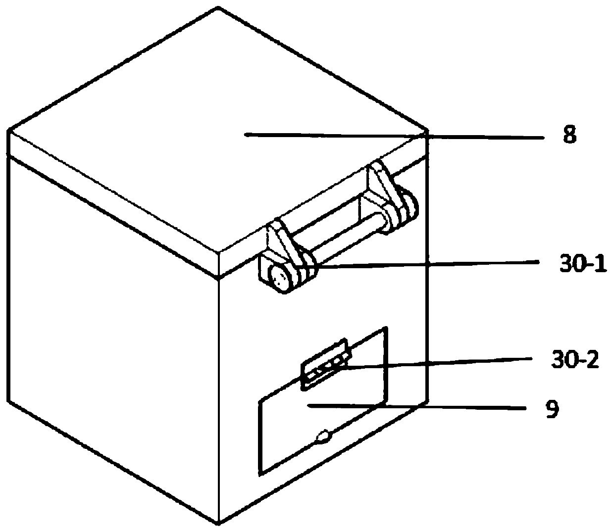
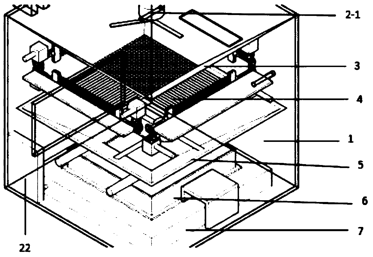
[0028] see Figure 1-2 , a sieve analysis test machine device, comprising a test machine shell 1, a hair dryer, a guide device 3, a net device 4, a funnel device 5, a collection box 6, a weighing device 7, and a processor 22; the test machine The casing 1 is located at the periphery of the sieve analysis test machine device, and is included in all devices; the first electric blower device 2-1 is located at the top of the sieve analysis test machine device, so that the sand particles can fully fall, and it is connected with the top of the sieve analysis test machine device. The upper cover 8 is welded through the connecting rod 14; the guide device 3 is located at the bottom of the first hair dryer 2-1, and the bottom is a buckle 12, which is nested in the square line 16 of the net device 4 below; the net The device 4 is located at the lower part of the guide device 3, and fil...


PUM


Abstract

The invention relates to a sieve analysis experimental machine, which comprises an experimental machine shell, an electric blowing device, a guide device, a net device, a funnel device, a collection box, a weighing device and a processor. The experimental machine shell is positioned on the outer periphery of the sieve analysis experimental machine; the electric blowing device is positioned on theupper portion of the sieve analysis experimental machine; the guide device is positioned below the electric blowing device; the net device is positioned below the guide device; the funnel device is positioned below the net device; the collection box is positioned below the funnel device; the weighing device is positioned below the collection box; the processor is positioned on an inner side of thesieve analysis experimental machine. By control of the net device, sieve analysis operation can be well carried out; by connection with a computer, sand diameters can be judged, a fineness modulus diagram is drawn, and sieve analysis experimental efficiency is guaranteed. In addition, by the sieve analysis experimental machine manual workload can be relieved, manpower resources are saved, and economic benefits and operating efficiency are improved.

Description

technical field [0001] The invention relates to the field of civil engineering materials, in particular to a sieve analysis test machine device. Background technique [0002] In the existing civil engineering material experiments, it is essential to measure the sand rate and draw the fineness modulus curve, and these operations are usually performed manually, which usually leads to errors. The remaining sand may be stuck in the square hole. If the next group of experiments is not careful, it will cause errors in the experimental data. If the next group of experiments is cleaned up, the experiment time will be extended; at the same time, calculate the sand rate and draw the fineness model. When calculating the curve, the amount of data is large, and the calculation is not easy; although the existing blower device can effectively vibrate the sand, the experimental operation is not easy, and it may cause some sand particles to break, and at the same time, the time cannot be eff...

Claims


Application Information

Patent Timeline
IPC IPC(8): G01N5/00G01N15/02
Inventor 封磊潘新科晏凤元左清媛何培玲牛龙龙张业茂姜志炜季雨航鲍煦文张智雅黄鑫冯磊彭张凯张林朱华俊李麟杰宋佳明徐少华
Owner NANJING INST OF TECH
Learn More