Electronic device and charging method thereof

A technology for electronic equipment and battery charging, which is applied to battery disconnect circuits, battery circuit devices, current collectors, etc. It can solve problems such as battery capacity waste and achieve the effect of improving utilization efficiency.

Inactive Publication Date: 2019-05-24
QINGDAO HISENSE MOBILE COMM TECH CO LTD
View PDF0 Cites 6 Cited by
  • Summary
  • Abstract
  • Description
  • Claims
  • Application Information

AI Technical Summary

Problems solved by technology

resulting in waste of battery capacity

Method used


Image

  • Electronic device and charging method thereof
  • Electronic device and charging method thereof
  • Electronic device and charging method thereof

Examples


Embodiment 1

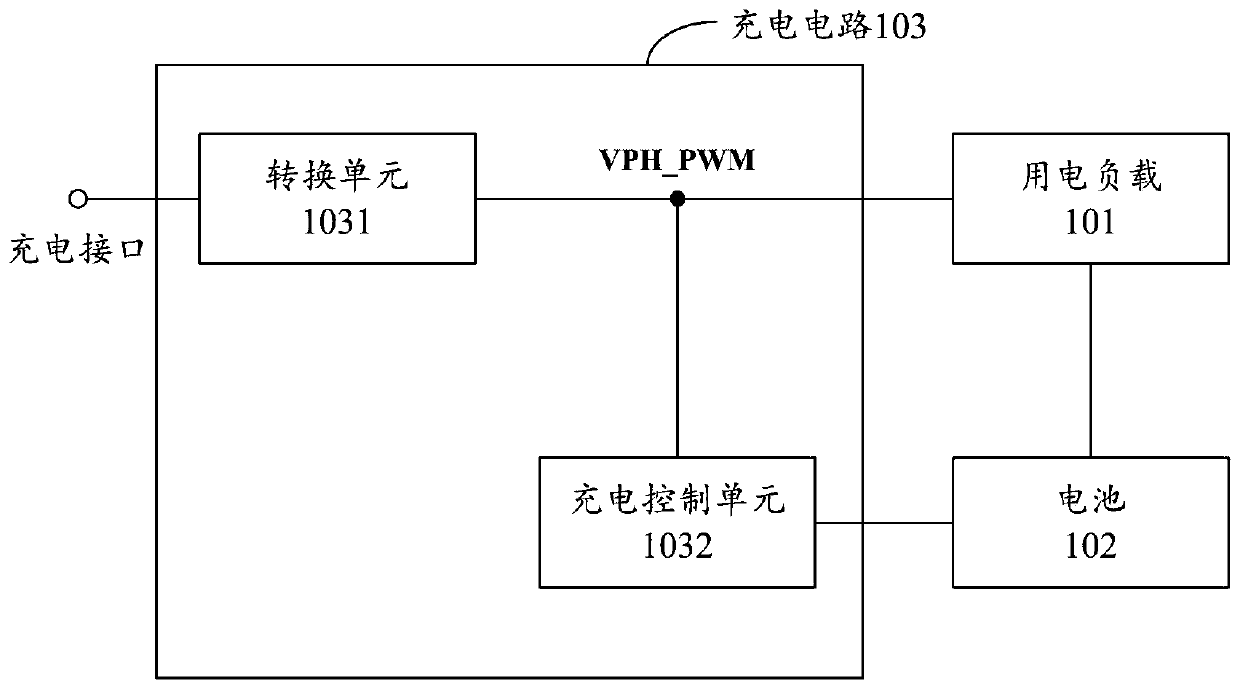
[0022] Such as figure 1 As shown, the embodiment of the present invention provides an electronic device, and the electronic device 10 includes a power load 101 and a battery 102 . Under normal circumstances, the electric load 101 is powered by the battery 102 to enable the electronic device 10 to complete corresponding functions. Wherein, the electric load 101 may specifically include devices such as display screens and processors in electronic equipment.

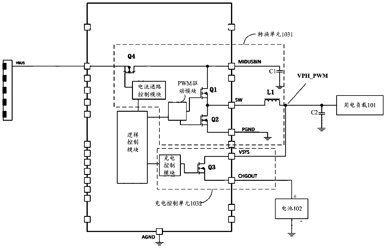
[0023] In addition, the electronic device 10 also includes a charging circuit 103 . The charging circuit 103 specifically includes: a conversion unit 1031 and a charging control unit 1032 . in,

[0024] The input end of the conversion unit 1031 is connected to the charging interface of the electronic device 10 , and the output end is connected to the node VPH_PWR with the input end of the charging control unit 1032 and the power input end of the electric load 101 . The output terminal of the charging control unit 1032 i...

Embodiment 2

[0067] The embodiment of the present invention also provides a method for charging an electronic device, which is applied to charge the electronic device 10 provided in the first embodiment above. Such as Figure 8 As shown, the method includes:

[0068] S301. Step down the voltage of the external power source connected to the charging interface of the electronic device, so as to charge the electric load and charge the battery.

[0069] S302. Stop charging the battery after the preset condition is met.

[0070] Optionally, S302 may specifically include:

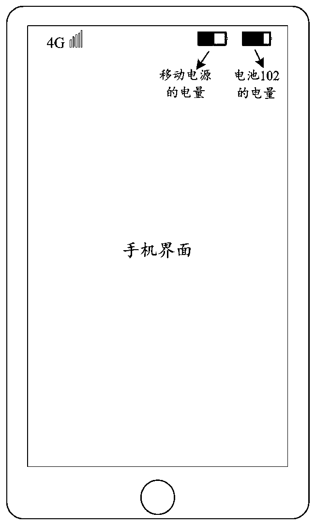
[0071] S302a. Stop charging the battery when it is detected that the external power source is a mobile power source and that the power of the battery is greater than the power threshold.

[0072] Alternatively, S302 may specifically include:

[0073] S302b. Stop charging the battery when a user's preset operation is detected.

[0074] For the method for charging an electronic device provided by the embodiment of the pres...


PUM


Abstract

The invention discloses an electronic device and a charging method thereof and relates to the technical field of electronic device power supply. After the electronic device is connected to an externalpower source, it can be selected whether the battery of the electronic device is charged by the external power source and the load of the electronic device is simultaneously powered by the external power source, or only the load of the electronic device is powered by the external power source. The electronic device includes an electric load, a battery, and a charging circuit. The charging circuitincludes a converting unit and a charging control unit. The converting unit is configured to reduce the voltage of the external power source input into the charging interface of the electronic deviceand to output the voltage from the output end of the converting unit to charge the electric load and charge the battery through the charging control unit. The charging control unit is configured to,after a preset condition is satisfied, disconnect a path between the input end and the output end of the charging control unit and to stop charging the battery through the charging control unit. The charging method is applied to power supply of the electronic device.

Description

technical field [0001] The invention relates to the technical field of electronic equipment power supply, in particular to an electronic equipment and a charging method thereof. Background technique [0002] With the technological development and widespread use of various smart electronic devices, users are increasingly dependent on electronic devices and using them more frequently. Since there has been no major breakthrough in the energy density of batteries, charging electronic devices with mobile power sources such as charging treasures has become a commonly used method to improve the battery life of electronic devices. [0003] However, when charging an existing electronic device, whether it is charged by a mobile power supply or by an adapter connected to a power socket, an external power source is generally used to charge the battery of the electronic device and provide power to the load of the electronic device. At this time, the current of the external power supply ...

Claims


Application Information

Patent Timeline
Patent Type & Authority Applications(China)
IPC IPC(8): H02J7/00
CPCH02J7/0032H02J7/0068
Inventor 尹荣贻陈冰
Owner QINGDAO HISENSE MOBILE COMM TECH CO LTD
Why Eureka
Try Eureka