

Power apparatus, power apparatus controlling method and controller
A technology of a power supply device and a control device, which is applied in the directions of power consumption devices, electric power devices, power devices, etc., can solve the problems of increased cost, obstacles to the development or practical application of on-board chargers, and increased vehicle space and weight. To achieve the effect of saving space, improving convenience, and reducing costs
- Summary
- Abstract
- Description
- Claims
- Application Information
AI Technical Summary
Problems solved by technology
Method used
Image

Examples
no. 1 Embodiment approach
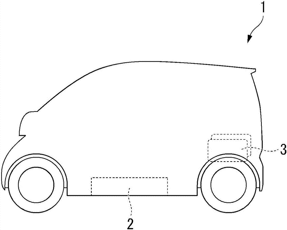
[0040] figure 1 It is a figure which shows an example of the transportation equipment provided with the power supply device in 1st Embodiment of this invention. exist figure 1In the present invention, a vehicle (such as an electric car) 1 is shown as an example of transportation equipment equipped with a power supply device, but the power supply device of the present invention can be applied to motorcycles, three-wheeled vehicles, four-wheeled motor vehicles, and hybrid vehicles with internal combustion engines and electric motors. Any vehicle such as a motor vehicle, a ship, an aircraft, etc.
[0041] The vehicle 1 includes, for example, a main battery pack (main power supply) 2 arranged at the bottom of the vehicle body and a plurality of sub battery packs (auxiliary power supply) 3 detachably provided at the rear of the vehicle body as power sources. exist figure 1 Although two auxiliary power supplies 3 are shown in the figure, three or more auxiliary power supplies may...
no. 2 Embodiment approach
[0089] Next, use Figure 9 A second embodiment of the present invention will be described. In the first embodiment, an example was described in which the discharge processing of the plurality of auxiliary power sources is controlled based on at least one of the voltage and charge rate of power storage unit 20 . However, since a power supply with a low resistance value tends to have higher output power than a power supply with a high resistance value, when there is a difference in the resistance value of each auxiliary power supply, only the voltage and the charging rate of the power storage unit 20 may be used. The control of multiple auxiliary power supplies will increase the SOC difference. Therefore, in this embodiment, an example in which the discharge process is controlled based on the resistance values and SOC of a plurality of auxiliary power supplies will be described. In the description of the second embodiment, the same reference numerals are attached to the same...
no. 3 Embodiment approach
[0101] Next, use Figure 11 and Figure 12 The third embodiment will be described. Compared with the first embodiment described above, the present embodiment is different in that the charging device 14 is omitted, and the main power supply 2 is charged using the electric power output from the auxiliary power supply 3 . Therefore, in the description of this embodiment, the same reference numerals are assigned to the same parts as those of the above-mentioned first embodiment, and the description thereof will be omitted or simplified.
[0102] Figure 11 It is a figure which shows an example of 5 A of power supply apparatuses in 3rd Embodiment. The power supply unit 5A has the figure 2 In the power supply device 5 shown, the charging device 14 is omitted, and a main switch 40 and a plurality of converters (first converter 42-1 to n-th converter 42-n) are further added.
[0103] The main switch 40 makes each of the first auxiliary power supply 3-1 to the nth auxiliary power...
PUM
 Abstract
Description
Claims
Application Information