Method for manufacturing shaped components
一种成型构件、构件的技术,应用在制造成型构件领域
- Summary
- Abstract
- Description
- Claims
- Application Information
AI Technical Summary
Problems solved by technology
Method used
Image

Examples
Embodiment Construction
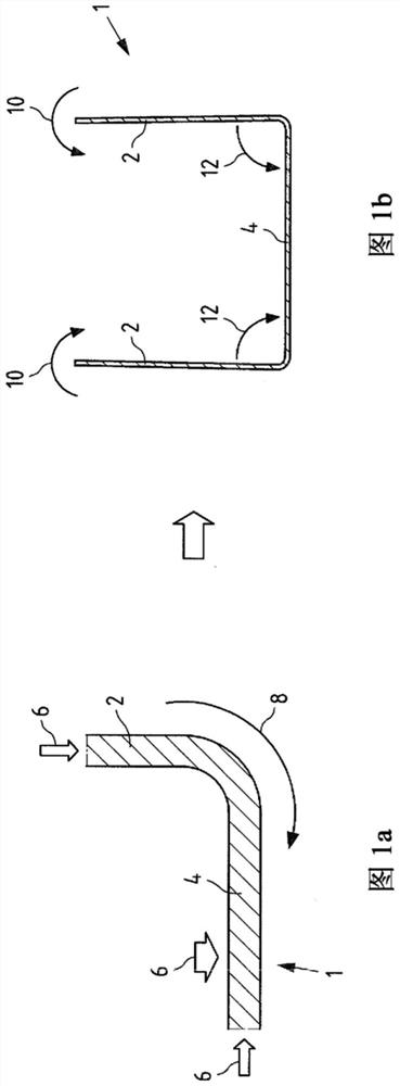
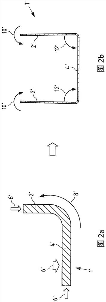
[0042] Figures 1, 2 respectively show schematic cross-sectional views of the side plate area 2, 2' and the bottom area 4, 4' of a component 1, 1' for illustrating an embodiment of the method for a component 1, 1' Effect.
[0043] Component 1 in Figure 1 has a bottom-specific material adaptation in the form of a material addition or upset allowance of +2%, and a side plate-specific material adaptation in the form of a material addition or upset allowance of +3% . As a result of the upsetting indicated by arrow 6 during the alignment process, material flows from the side plate area into the bottom area, as indicated by arrow 8 . have been determined by simulation and in Figure 1b As shown in , this results in a reduction in the side plate opening angle or the distance between the ends of the side plates (arrows 10, 12). As a result, a CAD-accurate bottom radius can be achieved, and the outward springback of the side plate area 2 can be counteracted, thereby improving dimensi...
PUM
 Abstract
Description
Claims
Application Information
 - R&D
- Intellectual Property
- Life Sciences
- Materials
- Tech Scout
- Unparalleled Data Quality
- Higher Quality Content
- 60% Fewer Hallucinations
Browse by: Latest US Patents, China's latest patents, Technical Efficacy Thesaurus, Application Domain, Technology Topic, Popular Technical Reports.
© 2025 PatSnap. All rights reserved.Legal|Privacy policy|Modern Slavery Act Transparency Statement|Sitemap|About US| Contact US: help@patsnap.com