
Passive Flow Direction Biasing in Low Temperature Thermosyphons

A flow direction, passive technology, applied in the direction of measuring devices, lighting and heating equipment, superconducting magnets/coils, etc., can solve the problem of high cost of liquid helium, and achieve the effect of efficient heat exchange

Active Publication Date: 2021-06-22
KONINKLJIJKE PHILIPS NV
View PDF6 Cites 0 Cited by
  • Summary
  • Abstract
  • Description
  • Claims
  • Application Information

AI Technical Summary

Problems solved by technology

However, the liquid helium required for this method is expensive and requires liquid helium to be available when the magnet is activated

Method used


Image

  • Passive Flow Direction Biasing in Low Temperature Thermosyphons
  • Passive Flow Direction Biasing in Low Temperature Thermosyphons
  • Passive Flow Direction Biasing in Low Temperature Thermosyphons

Examples


Embodiment Construction

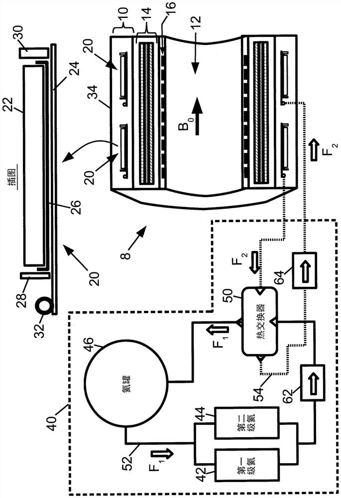
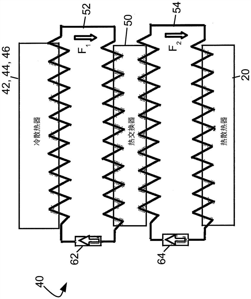
[0022] In the heat exchanger, the hotter coolant fluid flows in a flow path close to the flow path carrying the cooler coolant fluid, and heat is transferred from the hotter coolant fluid to the cooler coolant fluid, reducing The temperature of the hotter coolant fluid. In a heat exchanger, the flow of hotter coolant fluid through its flow path may be parallel to the flow of cooler coolant fluid through its flow path. Alternatively, the flow of the hotter coolant fluid through its flow path may be antiparallel to (ie, in the opposite direction of) the flow of the cooler coolant fluid through its flow path. The latter arrangement is known as a counterflow arrangement and is more efficient than a parallel flow arrangement because the average temperature difference at points along the parallel flow path is higher.

[0023] This paper recognizes that a problem with existing thermosiphon cooling installations that employ primary and secondary coolant circuits connected by heat exc...


PUM


Abstract

A cooling device (40) comprising: a heat exchanger (50); a first flow circuit (52) connecting cold radiators (42, 44, 46) and the heat exchanger; and a second flow circuit (54) ), which connects the heat radiator (20) and the heat exchanger. A first passive one-way valve (62) provided on the first flow circuit is oriented to allow in the permitted flow direction (F 1 ) and block flow in the opposite direction. A second passive one-way valve (64) provided on the second flow circuit is oriented to allow in the permitted flow direction (F 2 ) and block flow in the opposite direction; the permissible flow direction creates a counterflow in the heat exchanger. In the illustrative embodiment, the thermal heat sink includes a cryogenic magnet coil (20), and the thermal heat sink is a cold head (42, 44) and a liquid helium tank (46).

Description

technical field [0001] The following generally relates to cooling technology, cryogenic cooling technology, superconducting magnet technology, superconducting magnet magnetic resonance imaging (MRI) equipment technology, and the like. Background technique [0002] Some commercial magnetic resonance imaging (MRI) equipment employs superconducting magnet windings to provide the necessary high-intensity static (B 0 ) efficient generation of magnetic field. Traditionally, such magnets are immersed in liquid helium to keep the superconducting material below its critical superconducting temperature. However, the liquid helium required for this method is expensive and requires the availability of liquid helium when the magnet is activated. [0003] Another known method for cooling superconducting magnets employs thermosiphons. A superconducting magnet is placed in a vacuum dewar to maintain thermal isolation on a thermally conductive (eg, copper) substrate cooled by a cryogenic ...

Claims


Application Information

Patent Timeline
Patent Type & Authority Patents(China)
IPC IPC(8): F25B9/10F25B25/00H01F6/04
CPCF25B9/10F25B25/005H01F6/04F25B41/20F25B9/002G01R33/3804G01R33/3815
Inventor M·福斯
Owner KONINKLJIJKE PHILIPS NV
Learn More