Optical lens system

A lens optics and lens technology, applied in the field of lens optical system, can solve the problem of difficult to design a wide image angle, etc., and achieve the effect of excellent economy

Inactive Publication Date: 2019-05-24
ELCOMTEC
View PDF14 Cites 0 Cited by
  • Summary
  • Abstract
  • Description
  • Claims
  • Application Information

AI Technical Summary

Problems solved by technology

However, it is difficult to design a lens that has a wide image angle, can be used in combination with a high-definition image sensor, and has excellent optical performance such as aberration and distortion.

Method used


Image

  • Optical lens system
  • Optical lens system
  • Optical lens system

Examples


Embodiment Construction

[0044] Hereinafter, embodiments of the present invention will be described in detail with reference to the accompanying drawings. During the description of the present invention, if it is considered that adding a specific description to a technique or feature known in the corresponding field will obscure the technical idea of ​​the present invention, a part of it will be omitted from the detailed description. Also, the terms used in the present specification are terms used to appropriately express the embodiments of the present invention, and may be changed according to the relevant persons in the corresponding field or the practice or the like. Therefore, the definition of this term should be given based on the content of the overall scope of this specification.

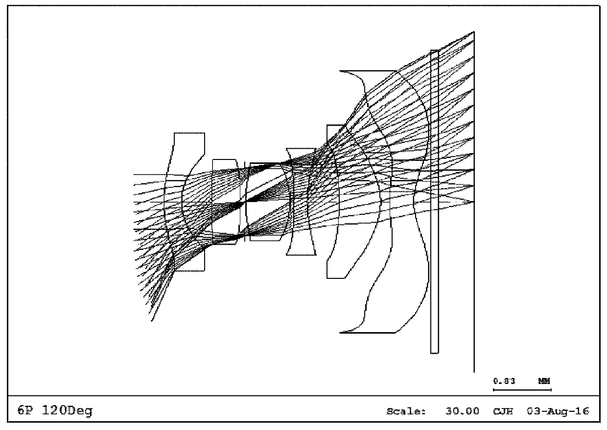
[0045] Below, refer to figure 1 The lens optical system of the first embodiment of the present invention will be described.

[0046] figure 1 It is a lens structure diagram of the lens optical system which concer...


PUM

PropertyMeasurementUnit
refractive indexaaaaaaaaaa

Abstract

The present invention discloses an optical lens system. An optical lens system according to the present invention can be installed in a camera module and be used for capturing an image. An optical lens system according to the present invention comprises a first lens, a second lens, a third lens, a fourth lens, a fifth lens and a sixth lens arrayed between an object and a sensor, on which an imageof the object forms, sequentially from the object side to the sensor side. The first lens has a negative refractive power. The second lens has a positive refractive power. The third lens has a positive refractive power, and the object-side surface of the third lens is convex at a radical axis. The fourth lens has a refractive power. The object-side surface of the fourth lens is convex at a radicalaxis and is concave in the periphery within an effective diameter of the radical axis. The sensor-side surface of the fourth lens is concave at the radical axis. The object-side surface and sensor-side surface of the fourth lens are both aspheric surfaces. The fifth lens has a positive refractive power, and the object-side surface of the fifth lens is concave at a radical axis and is an asphericsurface. The sixth lens has a refractive power. The sensor-side surface of the sixth lens is concave and has at least one inflection point within an effective diameter. The object-side surface and sensor-side surface of the sixth lens are both aspheric surfaces. A diaphragm is positioned between the second lens and third lens. [theta] is a viewing angle in a diagonal direction of the optical lenssystem. F is a focal length of the optical lens system. TTL is a length along an optical axis from the object-side surface of the first lens to the sensor. BFL is a length along an optical axis from the sensor-side surface of the sixth lens to the sensor. And the following conditional expressions are satisfied. Conditional expressions: -1.00<tan[theta]/f<-0.80 4.0< TTL/BFL<6.0

Description

technical field [0001] The present invention relates to a lens optical system, and more specifically, to a lens optical system that can be mounted on an imaging camera module. Background technique [0002] The camera module for imaging includes: a lens optical system including at least one lens; and an image sensor that receives light passing through the lens optical system and converts it into an electrical signal. A solid-state imaging element such as a charge coupled device (CCD) or a complementary metal oxide semiconductor image sensor (CMOS image sensor) is generally widely used as an image sensor. [0003] Recent camera modules are widely used in electronic devices such as smart phones, palmtop computers, and laptop computers. In order to improve the convenience and aesthetics of users, such electronic devices tend to be smaller and thinner. In addition, the conventional camera apparatuses also tend to be smaller and thinner. Therefore, the camera module mounted in ...

Claims


Application Information

Patent Timeline
Patent Type & Authority Applications(China)
IPC IPC(8): G02B9/62G02B1/04H04N5/374
CPCG02B1/041G02B13/0045H04N25/76G02B9/62G02B13/04G02B5/005G02B13/18H04N23/55
Inventor 金世振赵在勋姜善明
Owner ELCOMTEC
Why Eureka
Try Eureka