

Instrument trolley applied to operation room to accommodate instruments
A technology for instrument tables and operating rooms, which is applied in the field of instrument trolleys for placing instruments in operating rooms. It can solve the problems of trolleys occupying space, increasing the burden on medical staff, and fatigue of medical staff, so as to save space and facilitate cleaning and processing. Garbage, space-saving effect
- Summary
- Abstract
- Description
- Claims
- Application Information
AI Technical Summary
Problems solved by technology
Method used
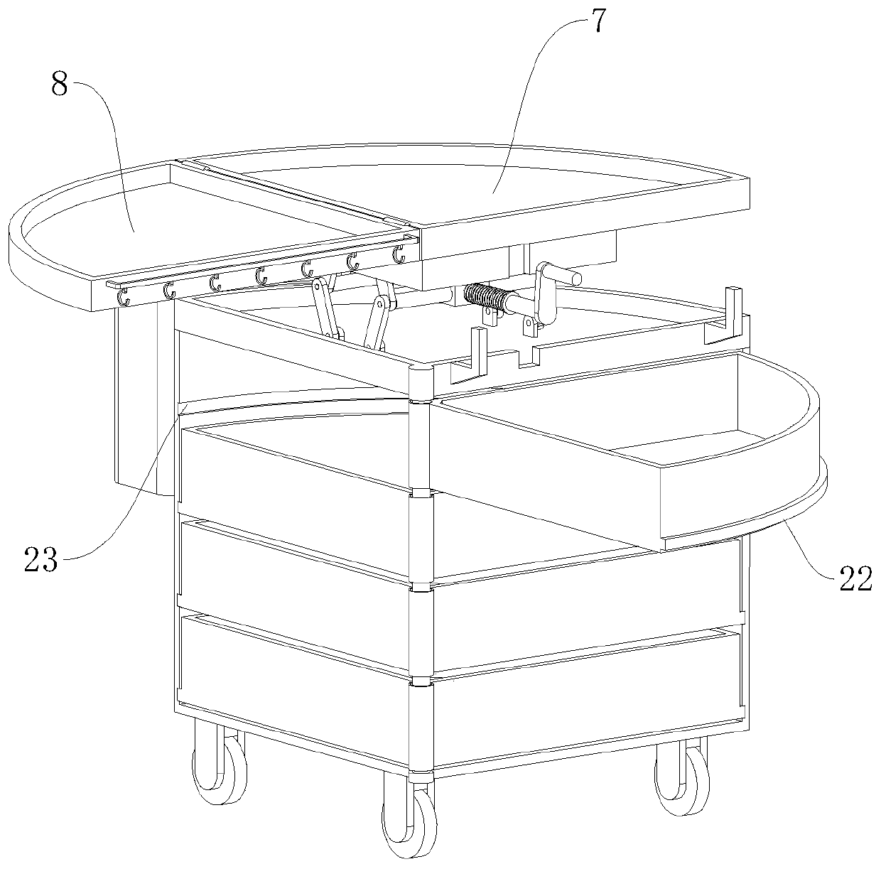
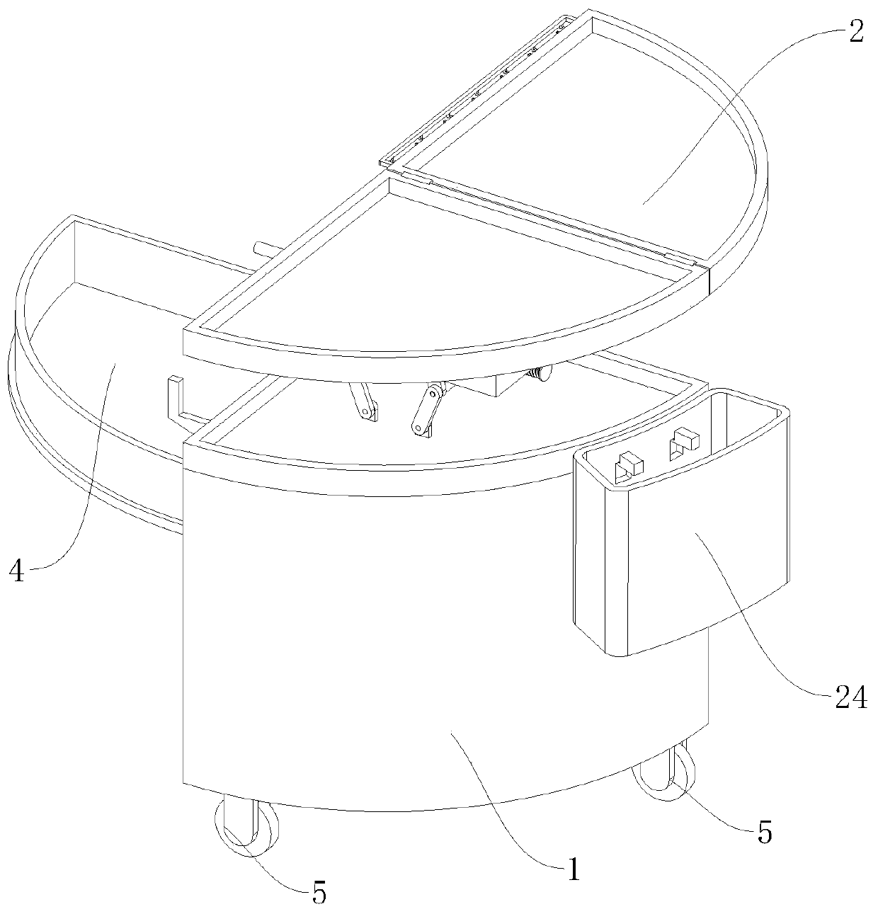
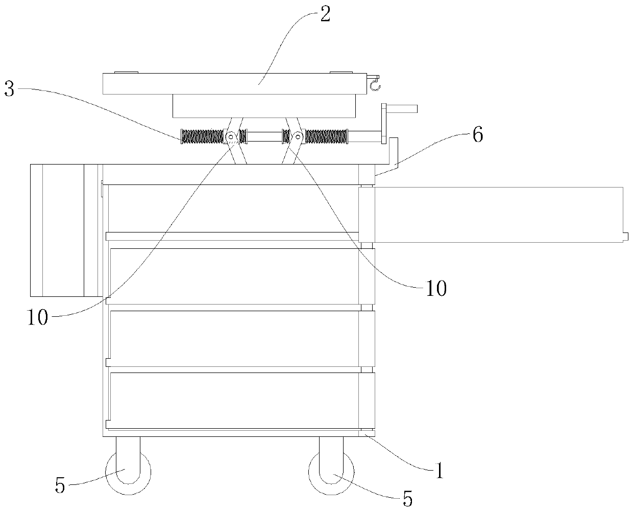
Image

Examples
Embodiment Construction
[0022] Several embodiments of the present invention will be disclosed in the following drawings. For clear description, many practical details will be described in the following description. However, it should be understood that these practical details should not be used to limit the present invention. In other words, in some embodiments of the present invention, these practical details are unnecessary. In addition, in order to simplify the drawings, some conventionally used structures and components will be shown in simple schematic ways in the drawings.
[0023] In addition, the descriptions related to "first", "second", etc. in the present invention are only used for descriptive purposes, and do not specifically refer to the order or sequence, nor are they used to limit the present invention. They are only used to distinguish between The same technical terms describe only the components or operations, but cannot be understood as indicating or implying their relative importanc...
PUM
 Abstract
Description
Claims
Application Information