
Die casting mold with connecting rod body cavity liquid inlet multi-flow channel structure

A die-casting mold and multi-channel technology, which is applied to the field of die-casting molds with multi-channel structure for connecting rod body cavity, which can solve the problems of slow filling speed, large heat loss of aluminum alloy melt, dissatisfaction of connecting rod body cavity filling, etc. problem, achieve the effect of preventing damage and facilitating demoulding

Pending Publication Date: 2019-05-28
重庆环鹰机械有限公司
View PDF0 Cites 3 Cited by
  • Summary
  • Abstract
  • Description
  • Claims
  • Application Information

AI Technical Summary

Problems solved by technology

[0002] When carrying out liquid die forging production of aluminum alloy connecting rods, one aluminum alloy connecting rod die-casting production mold can often die-cast and produce multiple aluminum alloy connecting rods at the same time. There is a main channel of melt in the mold, and there are multiple connecting rod body cavities on both sides of the main solution channel. The aluminum alloy melt is shunted from the solution main channel into the cavity of the connecting rod body for filling. The filling speed in the cavity of the connecting rod body is slow, resulting in a large heat loss of the aluminum alloy melt, which often leads to poor filling effect of the aluminum alloy melt in the mold, and the problem of dissatisfaction in the cavity of the connecting rod body, thus affecting product quality

Method used


Image

  • Die casting mold with connecting rod body cavity liquid inlet multi-flow channel structure
  • Die casting mold with connecting rod body cavity liquid inlet multi-flow channel structure
  • Die casting mold with connecting rod body cavity liquid inlet multi-flow channel structure

Examples


Embodiment Construction

[0027] Embodiments of the technical solutions of the present invention will be described in detail below in conjunction with the accompanying drawings. The following examples are only used to illustrate the technical solutions of the present invention more clearly, and therefore are only examples, rather than limiting the protection scope of the present invention.

[0028] In the description of the present application, it should be understood that the orientation or positional relationship indicated by the terms "top", "bottom", "inner", "outer", etc. is based on the orientation or positional relationship shown in the drawings, and is only for the purpose of It is convenient to describe the present invention and simplify the description, but does not indicate or imply that the device or element referred to must have a specific orientation, be constructed and operate in a specific orientation, and thus should not be construed as limiting the present invention.

[0029] Such as ...


PUM


Abstract

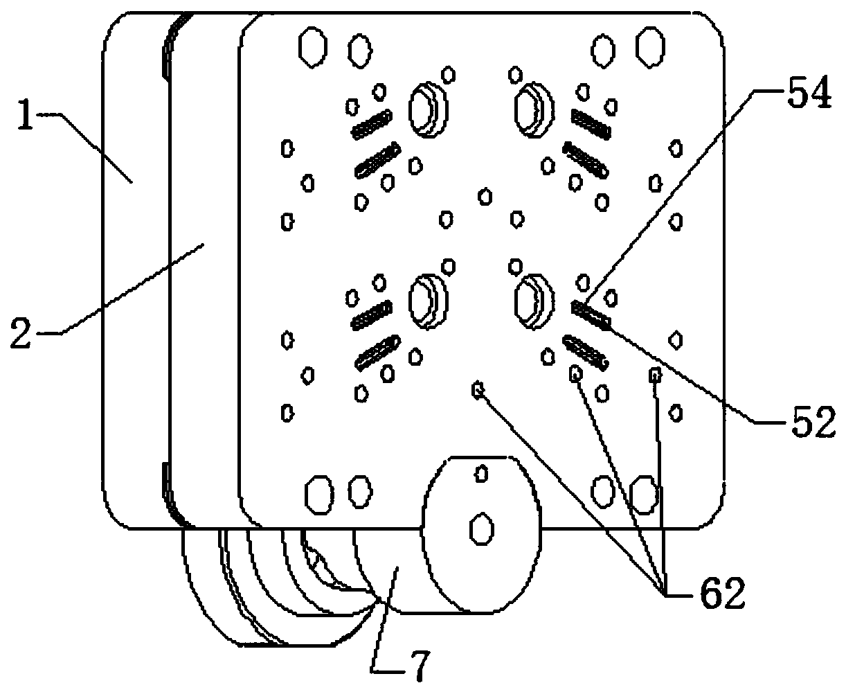
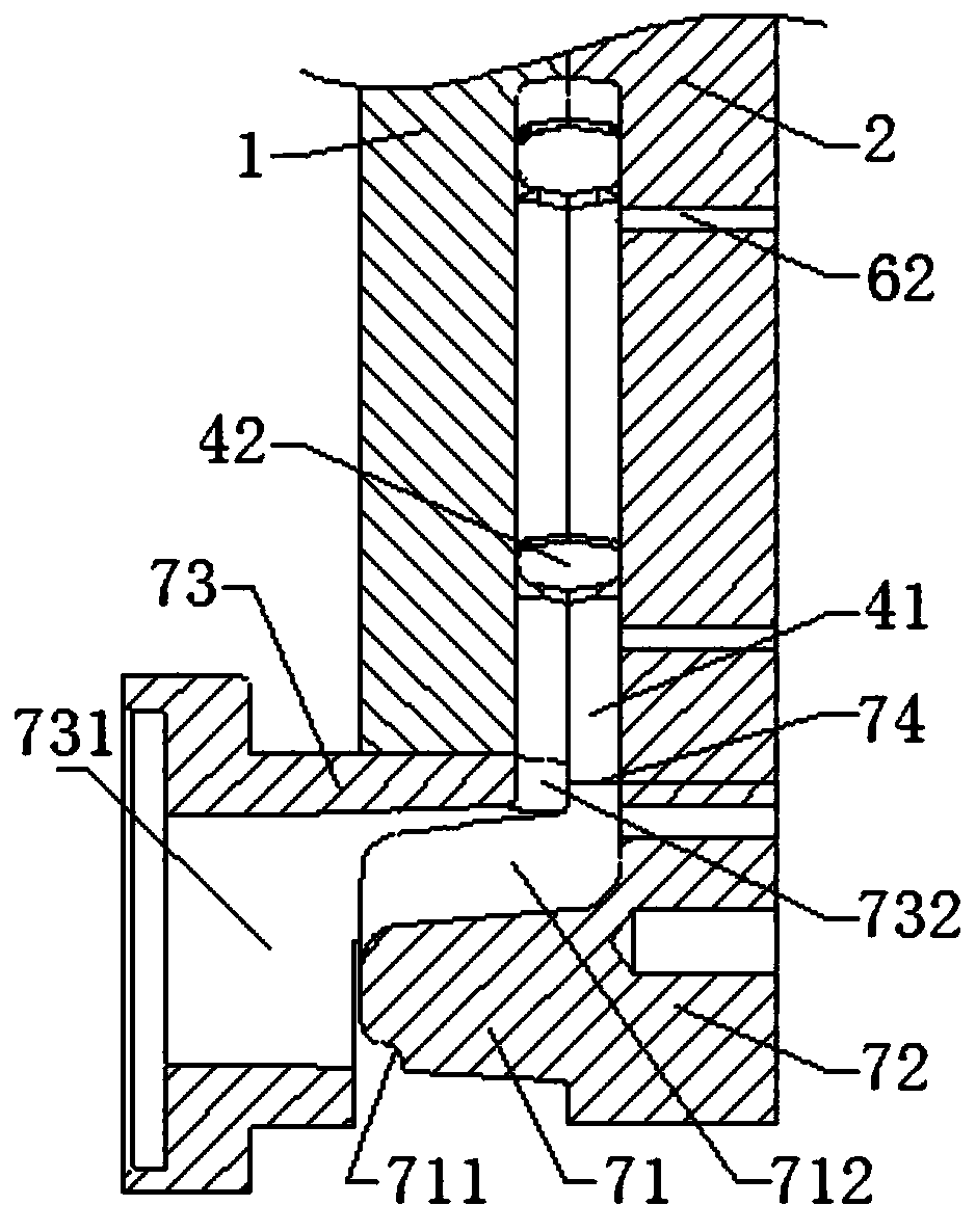
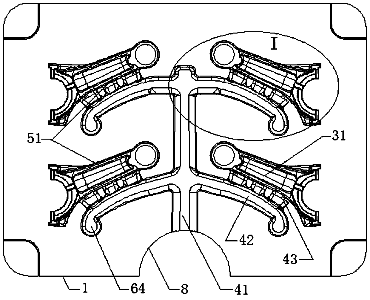
The invention provides a die casting mold with a connecting rod body cavity liquid inlet multi-flow channel structure. The die casting mold with the connecting rod body cavity liquid inlet multi-flowchannel structure comprises a fixed mold core and a movable mold core; the fixed mold core and the movable mold core surround to form a melt flow channel and multiple connecting rod body cavities inside; the melt flow channel comprises a primary main flow channel and multiple secondary main flow channels; each two of the multiple secondary main flow channels are symmetrically arranged on the two sides of the primary main flow channel; the primary main flow channel and the multiple secondary main flow channels are correspondingly distributed in the vertical direction and the transverse direction; the multiple connecting rod body cavities are correspondingly arranged on one sides of the multiple secondary main flow channels in a one-to-one corresponding manner; the extending directions of the connecting rod body cavities and the secondary main flow channels are as same as each other; multiple sub pouring flow channels are arranged between a rod body molding cavity of each connecting rodbody cavity and the secondary main flow channels; during die casting of the connecting rods, an aluminium alloy melt enters the connecting rod body cavities via multiple sub pouring flow channels; andtherefore, the melt filling speeds of the connecting rod body cavities are effectively increased. According to the die casting mold with the connecting rod body cavity liquid inlet multi-flow channelstructure, multiple aluminium alloy connecting rods can be simultaneously produced through die casting, it can be guaranteed that the melt is full of the connecting rod body cavities, and the qualification rate of connecting rod finished products can be increased.

Description

technical field [0001] The invention belongs to the technical field of die-casting production molds for aluminum alloy connecting rods, and in particular relates to a die-casting die with a multi-channel structure for feeding liquid into a cavity of a connecting rod body. Background technique [0002] When carrying out liquid die forging production of aluminum alloy connecting rods, one aluminum alloy connecting rod die-casting production mold can often die-cast and produce multiple aluminum alloy connecting rods at the same time. There is a main channel of melt in the mold, and there are multiple connecting rod body cavities on both sides of the main solution channel. The aluminum alloy melt is shunted from the solution main channel into the cavity of the connecting rod body for filling. The filling speed in the cavity of the connecting rod body is slow, resulting in a large heat loss of the aluminum alloy melt, which often leads to poor filling effect of the aluminum alloy...

Claims


Application Information

Patent Timeline
IPC IPC(8): B22D17/22
Inventor 张浩
Owner 重庆环鹰机械有限公司
Learn More