
Ventilation valve for vehicle

A technology for ventilation valves and vehicles, which is applied to vehicle components, control valves, balance valves, etc., and can solve problems such as weakened air flow and stagnant water areas

Pending Publication Date: 2019-05-28
ILLINOIS TOOL WORKS INC
View PDF2 Cites 2 Cited by
  • Summary
  • Abstract
  • Description
  • Claims
  • Application Information

AI Technical Summary

Problems solved by technology

Additionally, dead water areas are often created on the outside of the valve that impair airflow

Method used


Image

  • Ventilation valve for vehicle
  • Ventilation valve for vehicle
  • Ventilation valve for vehicle

Examples


Embodiment Construction

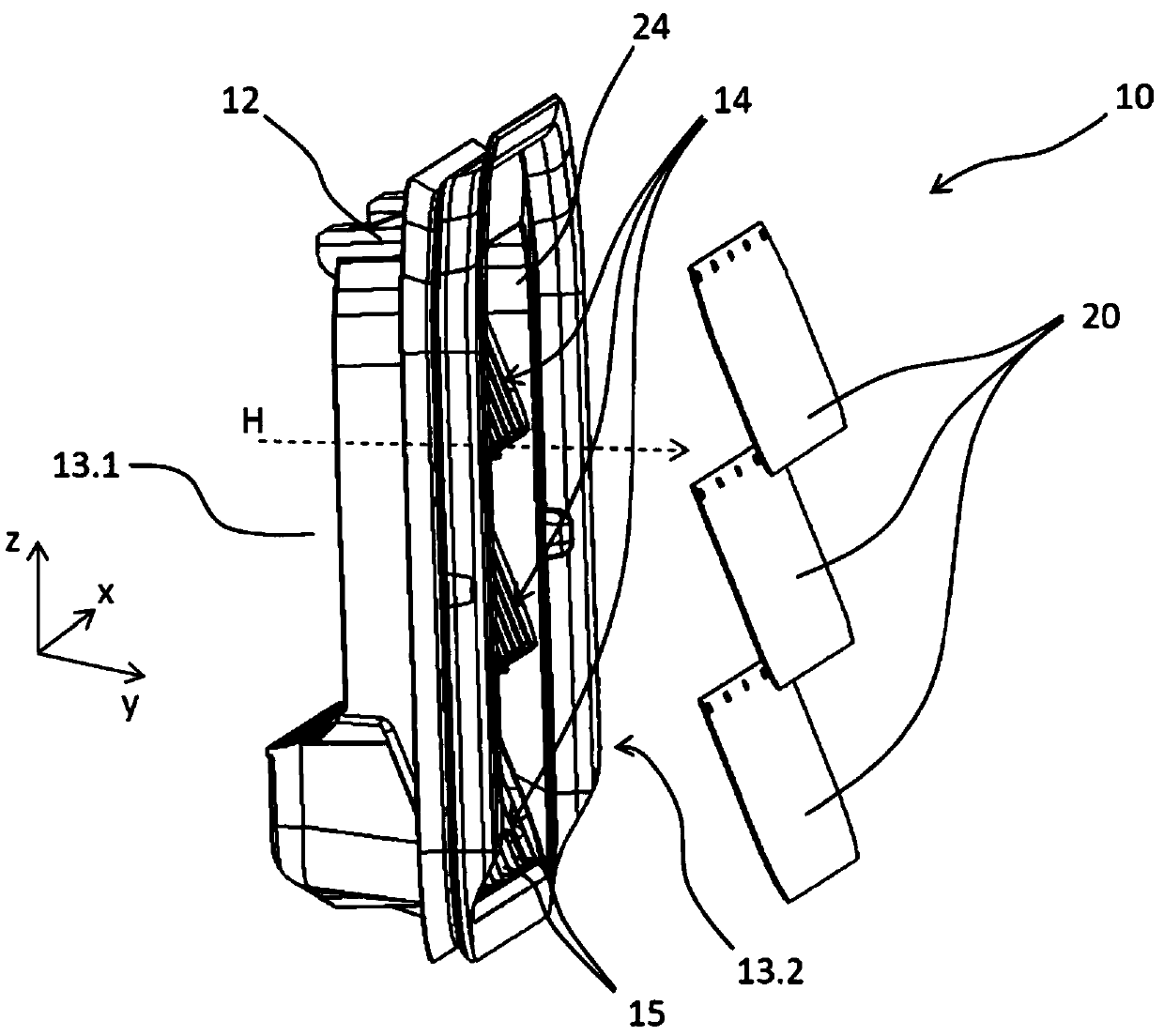
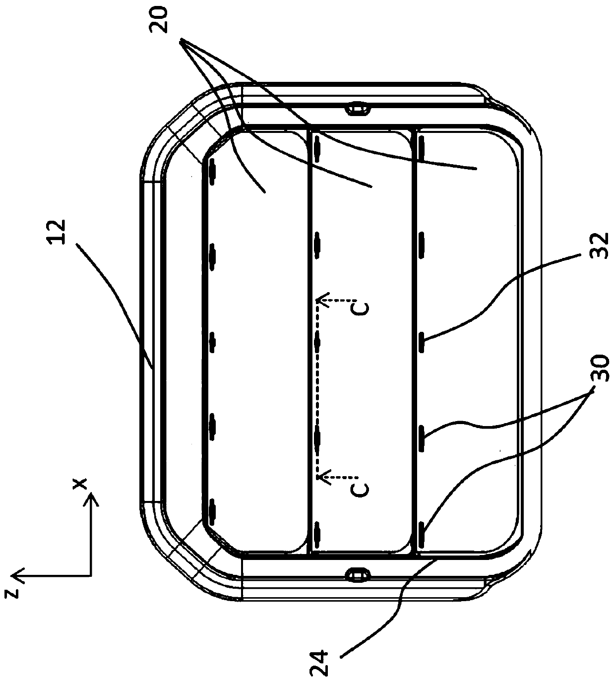
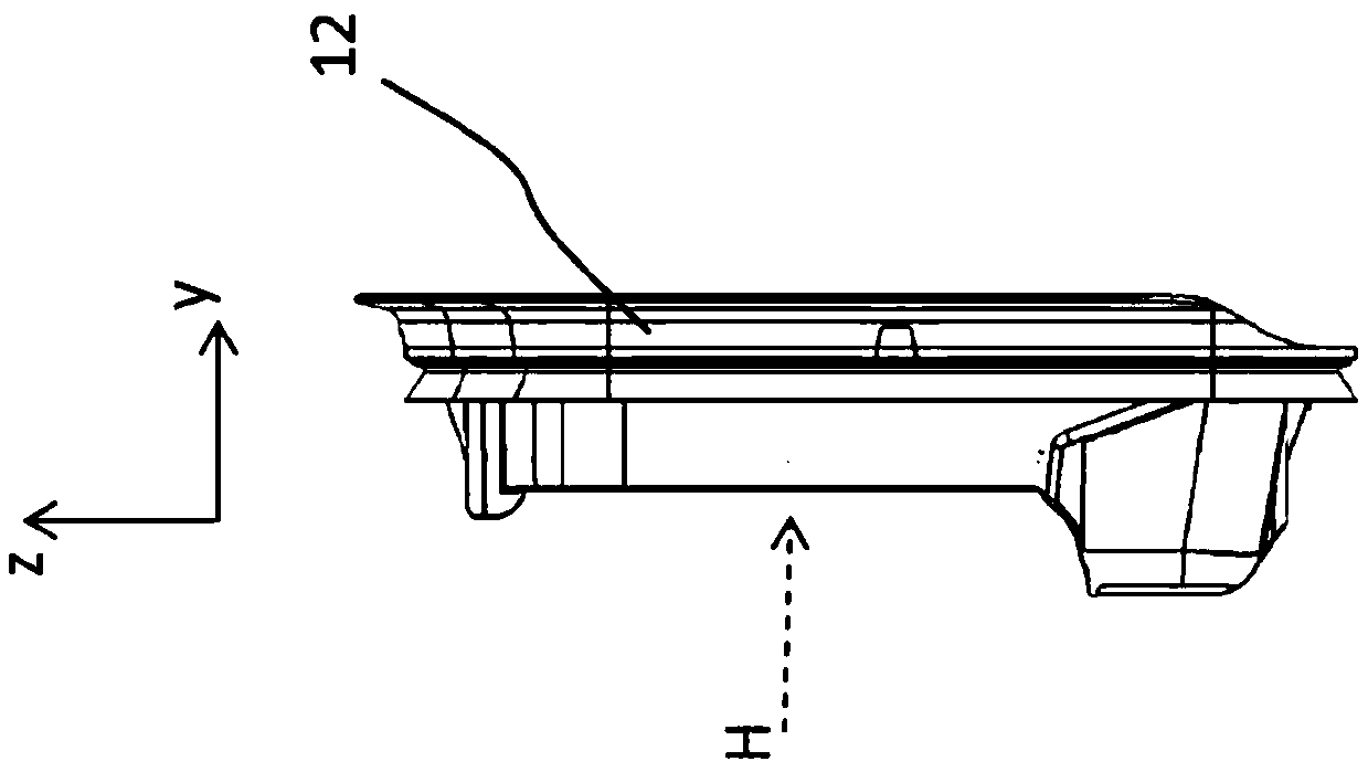
[0034] figure 1 An embodiment of the ventilation valve according to the invention is shown in a perspective view. The ventilation valve 10 comprises a valve frame 12 in which three openings 14 are formed. The ports 14 are each delimited by a wall 16 of the valve frame 12 and are spaced apart from each other by a connecting plate 18, in particular as Figure 4 with 5 visible in . The wall 16 is here also formed by webs 18 . A plurality of ribs 15 each extend through the through opening 14 . In the closed position of the ventilation valve 10 , the opening 14 is covered by the flap 20 , wherein the flap 20 bears against the wall 16 on the support surface 26 . In the present exemplary embodiment, the valve flap 20 is only in contact with the rib 15 when negative pressure prevails in the vehicle interior. To this end, the ribs 15 are set back slightly against the main flow direction H in their respective openings 14 . The flap 20 is of elastic design, for example made of rub...


PUM


Abstract

A ventilation valve for a vehicle for letting air out of a vehicle interior includes a valve frame with at least one through opening, and at least one valve flap which is mounted on the valve frame and is adjustable between a closed position and an open position. The at least one valve flap closes the at least one through opening in the closed position and opens up the at least one through openingin the open position. Air escaping through the at least one through opening flows from an air inlet side to an air outlet side along a main flow direction. A wall bounding the at least one through opening is inclined into the air flow in such a manner that the through opening tapers in the main flow direction.

Description

technical field [0001] The invention relates to a ventilation valve for ventilating the interior of a vehicle, comprising: a valve frame with at least one opening, and at least one flap mounted on the valve frame and positioned between a closed position and an open position adjustable, wherein at least one flap closes at least one port in the closed position and opens at least one port in the open position, wherein the air escaping through the at least one port flows from the air inlet along the main flow direction side flow to the air outlet side. Background technique [0002] Vent valves of this type are used to vent exhaust air from the interior of the vehicle in the event of a positive pressure inside the vehicle relative to the vehicle environment. Thus, air supplied to the interior of the vehicle, for example via the ventilation system, can be exhausted. In particular, sudden positive pressures in the vehicle interior (caused, for example, by closing a door or by tri...

Claims


Application Information

Patent Timeline
Patent Type & Authority Applications(China)
IPC IPC(8): B60H1/26
CPCB60H1/24B60H1/249B60H1/26F16K15/147F16K17/164
Inventor 海科·费希尔
Owner ILLINOIS TOOL WORKS INC
Learn More