Polarization imaging system point-by-point calibration method

A technology of polarization imaging and point-by-point calibration, which is applied in polarization spectrum, spectrum investigation, etc., can solve problems such as insufficient accuracy, low accuracy, and inability to meet the needs of use, so as to improve calibration accuracy, improve detection accuracy, and solve insufficient correction accuracy Effect

Active Publication Date: 2019-05-28
BEIJING INSTITUTE OF TECHNOLOGYGY
View PDF3 Cites 4 Cited by
  • Summary
  • Abstract
  • Description
  • Claims
  • Application Information

AI Technical Summary

Benefits of technology

This patented technology proposes an improved way to measure opaque surfaces by measuring their reflectivity or other properties through polarizing images taken from different angles around them. By comparing these measurements against known values stored within certain tables, it provides technical means that help make accurate measurement of such objects easier than current techniques like interference fringe analysis (IFA).

Problems solved by technology

This patented technical describes an improved technique called polarimetry that allows us to measure changes caused by external sources like sunlight without being affected by their own characteristics. By analyzing reflected signals through various techniques, we aim to improve the performance of polarimeters while reducing complexity and improving production costs.

Method used


Image

  • Polarization imaging system point-by-point calibration method
  • Polarization imaging system point-by-point calibration method
  • Polarization imaging system point-by-point calibration method

Examples


Embodiment 1

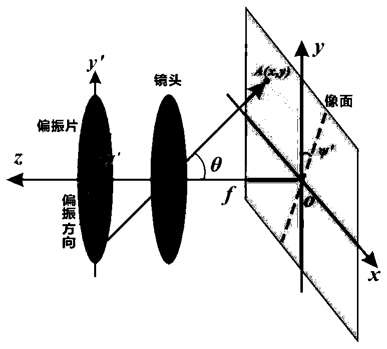
[0032] Taking the instrument matrix calibration of the Simultaneous Image Polarimetry with Double Separate Wallaston Primes as an example, the schematic diagram of the system is as follows: Figure 4 As shown, the experimental principle is as follows Figure 5 As shown, using the integrating sphere + rotating polarizer as a linearly polarized light source with controllable polarization state, the spectral transmittance curve of the polarizer and the relationship between the gray level of the camera and the illuminance are as follows: Figure 6 (a) and 6(b).

[0033] In this example, a four-channel polarization image composed of 36 groups of multiple pixels distributed in a matrix with a polarization angle of 0° to 350° every 10° is collected, and the image resolution is 640*512.

[0034] The specific implementation steps of this example are as follows:

[0035] Step 1. Collect 36 groups of four-channel polarization images, and perform image segmentation and registration;

...


PUM


Abstract

The invention relates to a polarization imaging system point-by-point calibration method and belongs to the technical field of polarization imaging. A plurality of sets of four-channel polarization images are collected through the polarization imaging system, and the ratio of the intensity of emergent light of an edge view field to the intensity of a center view field is calculated by applying a large-view-field axis external oblique light beam incident polarization imaging theory; the stokes vector of polarized light of the edge view field is obtained according to the normalized stokes vectorof the linearly polarized light of the center view field; then according to an instrument matrix and the relation between the stokes vectors and the channel intensity, a point-by-point instrument matrix of each set of four-channel images is obtained; finally, a least square method is applied to obtain the calibrated point-by-point instrument matrixes. According to the method, the calculated polarization degree and polarization angle information of a polarization imaging system calibrated by the point-by-point instrument matrixes are more accurate and approximate to theoretical values. Therefore, the problem that the precision of a traditional calibration method is insufficient is solved, detection errors of the polarization imaging system are reduced, and the precision of polarization imaging detection is improved.

Description


Claims


Application Information

Patent Timeline
Owner BEIJING INSTITUTE OF TECHNOLOGYGY
Why Eureka
Try Eureka