Light force cooling miniaturized high-precision optical gravity meter

A gravimeter, high-precision technology, applied to sensors and instruments for measuring the acceleration of gravity, and the field of optical cooling, miniaturized and high-precision optical gravimeter, which can solve the problems of large volume, complex reset, and many error factors. Effects of support changes, no initial velocity error, and reduced position uncertainty

Active Publication Date: 2019-05-28
ZHEJIANG UNIV
View PDF7 Cites 12 Cited by
  • Summary
  • Abstract
  • Description
  • Claims
  • Application Information

AI Technical Summary

Problems solved by technology

[0009] The existing gravity measurement method mainly uses the method of mechanically releasing the mass block, and uses the reset of the mass block to realize the repeated measurement of gravity. This measurement method has many shortcomings such as complex reset, large volume, and many error factors. However, according to the current optical Technological development, especially in the field of optical force and optical trap, continues to develop a new gravimeter technology based on these new technologies, so as to improve the measurement accuracy of gravity, reduce the complexity of the system, and achieve high gravity at the same time. Accurate and fast measurement method, so as to meet the urgent needs of gravity angular velocity measurement in the fields of inertial navigation, geodetic survey and mineral census

Method used

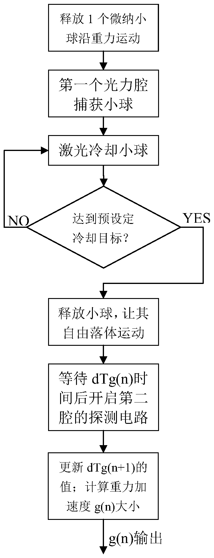

Image

  • Light force cooling miniaturized high-precision optical gravity meter
  • Light force cooling miniaturized high-precision optical gravity meter
  • Light force cooling miniaturized high-precision optical gravity meter

Examples


Embodiment Construction

[0061] Below in conjunction with accompanying drawing and embodiment the present invention will be further described:

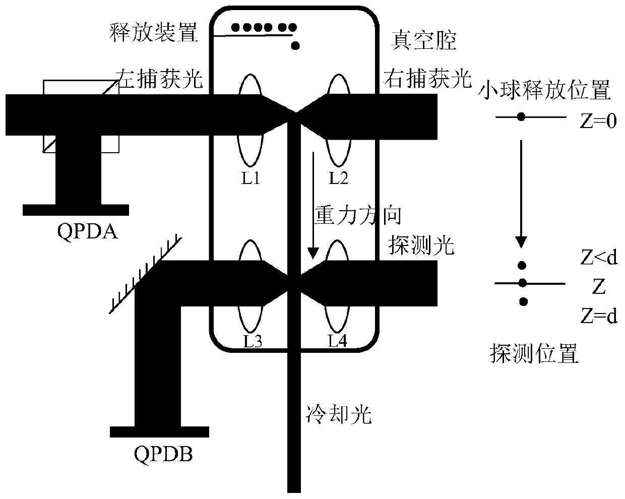
[0062] Such as figure 2 As shown, the gravimeter includes a vacuum chamber and a release device located in the vacuum chamber, a laser cooling chamber, an optical detection chamber and micro-nano balls; the release device is on the top of the vacuum chamber, and the initial micro-nano balls are loaded in the release device , the laser cooling cavity and the optical detection cavity are respectively located above and below the middle of the vacuum cavity, and the release position of the release device, the laser cooling cavity and the optical detection cavity are arranged in sequence from top to bottom along the vertical direction of gravity;

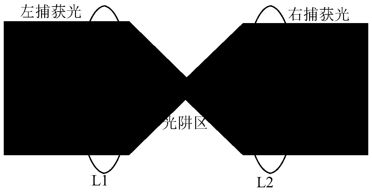
[0063] Such as figure 2 As shown, the laser cooling cavity is equipped with a laser capture device of micro-nano balls. The laser capture device includes two lenses L1 and L2 arranged horizontally opposite to the opt...


PUM


Abstract

The invention discloses a light force cooling miniaturized high-precision optical gravity meter. The gravity meter comprises a vacuum chamber, a release device, a laser cooling chamber, an optical detection chamber and a micro-nano ball; the laser cooling chamber and optical detection chambers are located above and below the middle of the vacuum chamber respectively; the laser cooling chamber comprises two lenses, and two horizontal parallel light beams adopt two vertical polarization states output by the same laser; focal points of the two lenses overlap with each other and form a light trapregion; the optical detection chamber comprises two lenses, the focal points of the two lenses overlap with each other at the focal point to form a detection region; the release device is provided with a release outlet, and a cooling light source is arranged under the vacuum chamber, and the cooling light source emits cooling light upwards to shine on the light trap region. Accordingly, the micro-nano ball is utilized as a measuring carrier, a laser cooling technology is combined, the release position and capture position of the ball are accurately measured to obtain a precise value of gravitational acceleration, environmental interference is eliminated, the gravitational acceleration measurement accuracy of gravity acceleration is improved, and the measuring speed and efficiency are improved.

Description

technical field [0001] The invention relates to a miniaturized high-precision optical gravimeter with optical cooling, belongs to the technical field of precision measurement, and belongs to a sensor and an instrument for measuring the acceleration of gravity. Background technique [0002] A gravimeter is a precision instrument used to measure the acceleration of gravity (gravity). It can be widely used in earth exploration, prospecting, surveying and other application fields, and is of great significance to the development of the national economy. The basic measurement principle of the gravimeter is based on Newton's second law, by detecting the free fall time dt and distance s of the mass block, and then according to g=2s / t 2 Obtain the measured value g of the acceleration due to gravity. [0003] The initial velocity of the mass block caused by the release process of the mechanical fixed structure at the beginning of the free fall process of the mass block, the gas distu...

Claims


Application Information

Patent Timeline
Patent Type & Authority Applications(China)
IPC IPC(8): G01V7/02G01V7/04
Inventor 陈杏藩祝训敏李楠胡慧珠舒晓武刘承
Owner ZHEJIANG UNIV
Why Eureka
Try Eureka