Short-circuit protection circuit

A technology of short-circuit protection circuit and holding circuit, which is applied in the protection of overcurrent response, etc., can solve the problems of non-recoverable fuse response, etc., and achieve the effect of long service life and low cost

Pending Publication Date: 2019-05-28
深圳市嘉昱机电有限公司
View PDF0 Cites 2 Cited by
  • Summary
  • Abstract
  • Description
  • Claims
  • Application Information

AI Technical Summary

Problems solved by technology

[0004] In view of the above problems, the present invention proposes a short-circuit protection circuit, which realizes short-circuit protection by using a ...

Method used


Image

  • Short-circuit protection circuit
  • Short-circuit protection circuit
  • Short-circuit protection circuit

Examples


Embodiment 1

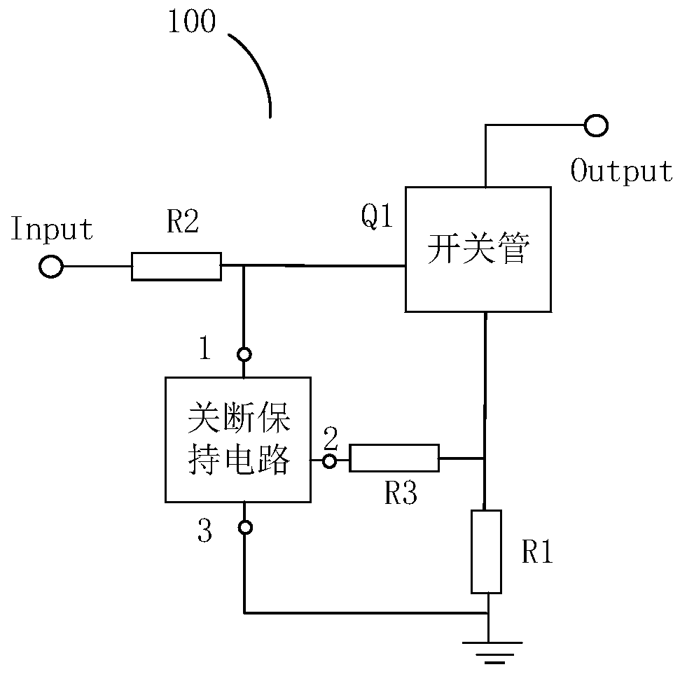
[0032] Please refer to figure 1 , this embodiment proposes a short-circuit protection circuit 100, which can be used for short-circuit protection of electrical signals and power output, and prevent damage to electrical equipment due to short-circuit. The short circuit protection circuit 100 will be described in detail below.

[0033] Such as figure 1 As shown, the short circuit protection circuit 100 includes a switch tube Q1, an off-hold circuit and an adjustment resistor R1. Wherein, the gate of the switching tube Q1 is connected to a control voltage input terminal Input, the source is connected to one end of the adjusting resistor R1, and the drain is used as a load connection terminal Output for connecting a load.

[0034] The first terminal 1 of the off-holding circuit is connected to the gate of the switching transistor Q1, the second terminal 2 is connected to the source of the switching transistor Q1, and the third terminal 3 is connected to the other end of the adju...

Embodiment 2

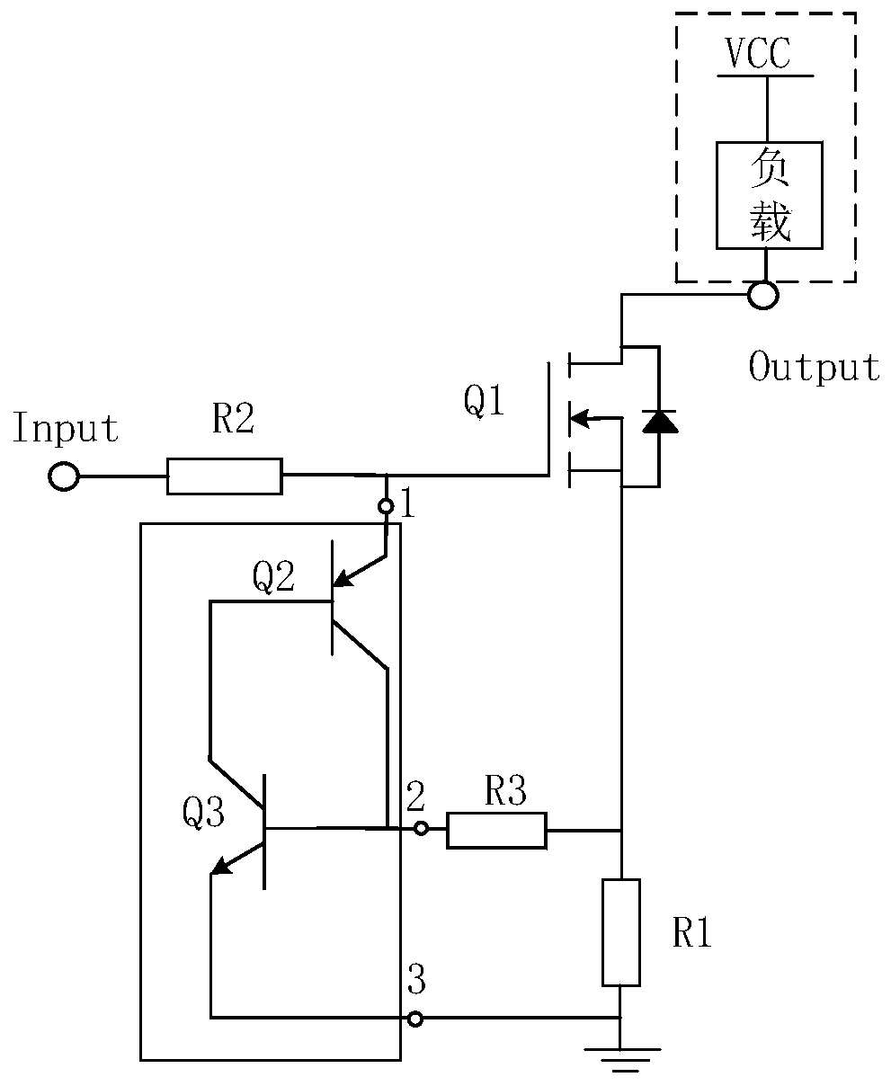
[0062] This embodiment also proposes a short-circuit protection circuit 100, which is different from the above-mentioned embodiments in that the switching transistor Q1' in this embodiment is a PMOS transistor, and the first transistor Q2' in the turn-off holding circuit is an NPN transistor. , the second transistor Q3' is a PNP transistor.

[0063] Specifically, such as Figure 4 As shown, when the switching transistor Q1' is a PMOS transistor, the collector of the PNP transistor in the off-holding circuit is connected to the base of the NPN transistor, and the collector of the NPN transistor is connected to the base of the PNP transistor. The emitter of the NPN transistor is connected to the first terminal 1 of the turn-off holding circuit, the base of the PNP transistor is connected to the second terminal 2 , and the emitter of the PNP transistor is connected to the third terminal 3 .

[0064] Such as Figure 4 As shown, when the switch tube Q1' is a PMOS tube, the first ...


PUM


Abstract

The invention discloses a short-circuit protection circuit, and the circuit comprises a switching tube, a turn-off holding circuit and an adjusting resistor. A grid electrode of the switching tube isconnected with a control voltage input end, wherein a source electrode is connected with one end of the adjusting resistor, and a drain electrode is used for connecting a load. A first end point of the turn-off holding circuit is connected with a grid electrode of the switching tube, a second end point is connected with a source electrode of the switching tube, and a third end point is connected with the other end of the adjusting resistor. The other end of the adjusting resistor is used for grounding or is connected with a power supply. According to the technical scheme, the short-circuit protection of load equipment can be achieved, the short-circuit protection device has the disconnection maintaining function and the power-on recoverable characteristic after short circuit occurs each time, the nanosecond-level short-circuit response speed can be achieved, the cost is low, and the service life is long.

Description

technical field [0001] The invention relates to the technical field of protection circuits, in particular to a short circuit protection circuit. Background technique [0002] During the actual use of electrical equipment, due to improper operation and other reasons, it is often easy to have a short circuit phenomenon, which may lead to damage to the electrical equipment. In the prior art, in order to provide short-circuit protection, most of them use a fuse, that is, a fuse, in the circuit. Since the fuse is heated and blown by itself, the connection of the circuit is disconnected to achieve the purpose of protecting the circuit. [0003] However, for the solution using fuses, first, it is irrecoverable. When the circuit is short-circuited every time, the fuse must be replaced with a new fuse to resume work after the fuse is blown. In the long run, it has a higher cost; two. The reason is that the fusing response is slow. Since the temperature of the internal fusing materi...

Claims


Application Information

Patent Timeline
IPC IPC(8): H02H3/08
Inventor 肖国庆
Owner 深圳市嘉昱机电有限公司
Why Eureka
Try Eureka