Light emitting diode (LED) short-circuit protection system

A short-circuit protection, LED light source technology, applied in the field of electronics, can solve the problems of lack of short-circuit protection, high cost of relays, low reliability, etc., and achieves the effects of low cost, simple circuit, and favorable promotion.

Active Publication Date: 2017-12-05
HEUVAN CHONGQING SCI TECH CO LTD
View PDF5 Cites 1 Cited by
  • Summary
  • Abstract
  • Description
  • Claims
  • Application Information

AI Technical Summary

Problems solved by technology

[0003] In the prior art, corresponding researches on LED short-circuit protection have been carried out in China to reduce the rigidity caused by such faults. For example, a Chinese patent application with publication number 103001179A discloses an LED lamp and its short-circuit protection circuit. Its main technical solution is to cut off the power circuit of the follow-up LED constant current circuit through the relay when the LED lamp is short-circuited, so as to play the role of short-circuit protection, but the cost of the relay in this technical solution is high and the noise is large
Another example: the Chinese patent application with the publication number of 101959352A discloses an LED drive circuit with LED short-circuit protection. The main technical solution includes the LED short-circuit protection circuit module, and the N -MOS tube, when the LED is short-circuited, it will drive the N-MOS tube to turn off, and then play a role in short-circuit protection, but the disadvantage of this method is that the circuit of the entire technical solution is complicated and the reliability is not high, so a A new LED short-circuit protection device, which can solve the problem that the short-circuit cannot be protected in the power output LED system

Method used


Image

  • Light emitting diode (LED) short-circuit protection system
  • Light emitting diode (LED) short-circuit protection system
  • Light emitting diode (LED) short-circuit protection system

Examples


no. 1 example

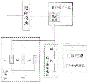
[0037] Such as figure 1 , 2 As shown, in this embodiment, when the load LED light source is short-circuited, a large instantaneous current will be output at the moment of short-circuit. Setting the first locking circuit between them can increase the impedance of the load, reduce the impact of the instantaneous current generated at the moment of short circuit, and make the voltage and current decrease slowly synchronously, and then transmit the collected short circuit signal to the signal processing unit through the signal acquisition unit. The signal processing unit judges the short-circuit signal according to the received signal. The signal processing unit issues a control command after determining that a short-circuit fault occurs in the system, and locks all outputs of the power module through the first locking circuit. The load stops working, and the power module and the power module are disconnected. The connection between loads realizes short-circuit protection for load...

no. 2 example

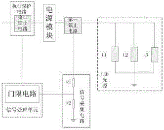
[0039] Such as image 3 , 4 As shown, the difference between this embodiment and the first embodiment is that the execution protection unit also includes a second locking circuit arranged at the input terminal of the power module for controlling the power module to stop working. In this embodiment, the signal processing The unit receives the short-circuit signal from the signal acquisition circuit, judges the short-circuit signal, and issues a control command, locks the power module through the second locking circuit, and controls the power module and the load to stop working.

no. 3 example

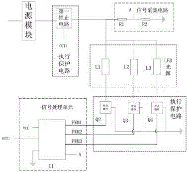
[0041] Such as Figure 5 , as shown in 6, the difference between this embodiment and the above two embodiments is that this embodiment is suitable for application in the LED light source lighting system with output control function, and it can be short-circuit protected. In this embodiment In the implementation protection circuit, under the control of the signal processing unit, the input terminal of the power module, the output terminal of the power module, and the control input terminal of the LED light source can respectively perform corresponding short-circuit protection according to the actual use system, through the short-circuit protection module. The controller protection circuit disconnects the connection between the load LED light source and the signal processing unit when a short circuit fault occurs in the system, and the controller protection circuit is set between the load LED light source and the signal processing unit, wherein the output load of the LED light so...


PUM


Abstract

The invention provides a light emitting diode (LED) short-circuit protection system. The LED short-circuit protection system comprises a power module, an execution protection unit, a signal acquisition unit and a signal processing unit, wherein the power module is used for supplying power to a load LED light source and a circuit, the execution protection circuit is used for performing outage protection on the system when a short-circuit fault occurs in the load LED light source, the signal acquisition unit is used for acquiring a short-circuit signal in real time to detect the system, and the signal processing unit is used for judging the short-circuit fault according to the acquisition signal of the signal acquisition unit and controlling the execution protection unit to perform short-circuit protection. By the LED short-circuit protection system, the problem that a power output LED system cannot be protected in short circuit can be solved, a power supply or a control circuit can be locked when an output LED is circuit-shorted, the short-circuit protection of the power output multi-path LED system is achieved, a large current is simultaneously prevented from instantaneously being output in short circuit, a circuit component is prevented from being broken down by an instantaneous current, a load such as the LED is protected, and the power supply and a subsequent circuit part also can be prevented from being damaged. The LED short-circuit protection system has the characteristics of simple circuit, relatively low cost and high reliability and is beneficial for promotion.

Description

technical field [0001] The invention relates to the field of electronics, in particular to an LED short-circuit protection system. Background technique [0002] LED (light emitting diode, light-emitting diode) is called the fourth generation light source, with energy saving, environmental protection, safety, long life, low power consumption, low heat, high brightness, waterproof, miniature, shockproof, easy dimming, concentrated beam, maintenance It is simple and convenient, and can be widely used in various indications, displays, decorations, backlights, general lighting and other fields. LEDs are widely used as lighting sources, but LEDs often have short circuits when they work abnormally. Short-circuit protection needs to be added to the circuit, so as to provide effective protection after the LED is short-circuited and prevent the fault from expanding further. [0003] In the prior art, corresponding researches on LED short-circuit protection have been carried out in Ch...

Claims


Application Information

Patent Timeline
Patent Type & Authority Applications(China)
IPC IPC(8): H05B33/08H05B44/00
CPCH05B45/00Y02B20/30
Inventor 沙玉峰唐开锋雷志强
Owner HEUVAN CHONGQING SCI TECH CO LTD
Why Eureka
Try Eureka