Protection circuit and biological sample preparation device

A technology for protecting circuits and preparing devices, which is applied in the direction of emergency protection circuit devices, circuit devices, emergency protection devices with automatic disconnection, etc., can solve problems such as short circuits, and achieve the effect of short circuit protection

Active Publication Date: 2022-05-13
RWD LIFE SCI
View PDF5 Cites 1 Cited by
  • Summary
  • Abstract
  • Description
  • Claims
  • Application Information

AI Technical Summary

Problems solved by technology

[0004] The embodiment of the present invention provides a protection circuit, which aims to solve the problem of short circuit between any metal terminals and any electrical circuits of the equipment with exposed metal terminals in the prior art

Method used


Image

  • Protection circuit and biological sample preparation device
  • Protection circuit and biological sample preparation device
  • Protection circuit and biological sample preparation device

Examples


Embodiment 1

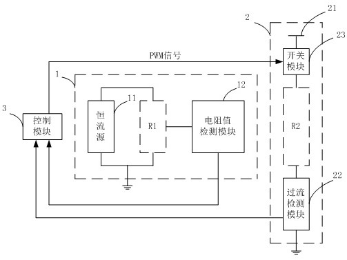
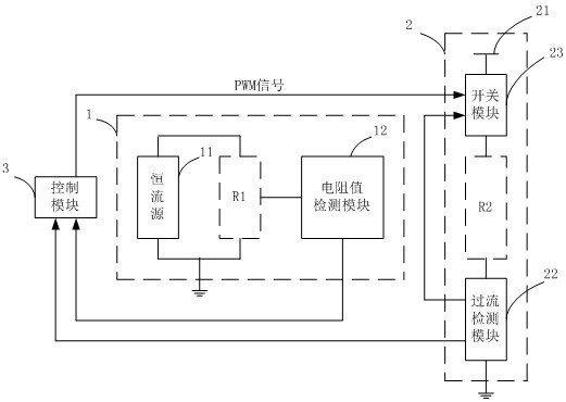
[0024] figure 1 is a schematic diagram of the protection circuit provided by Embodiment 1 of the present invention. Such as figure 1 As shown, the protection circuit includes a first loop 1 , a second loop 2 and a control module 3 .

[0025] In the embodiment of the present invention, the first loop 1 includes a constant current source 11 and a resistance value detection module 12 . The constant current source 11 is the excitation source of the first loop 1, and the voltage for forming the circuit of the constant current source 11 is a low voltage that will not cause harm to the human body, such as 3.3V. Connected to both ends of the constant current source 11 is the first load resistor R1 , and the first load resistor R1 varies according to the load actually connected to the first loop 1 . The resistance value detecting module 12 detects the load resistance value at both ends of the constant current source 11 , that is, detects the resistance value of the first load resist...

Embodiment 2

[0041] In many experiments in biology, it is usually necessary to simulate the body temperature of organisms or maintain a specific temperature during the preparation of biological samples to facilitate the conduct of biological experiments. And it is required that the heating of a single experimental container will not affect other operations of the biological experiment.

[0042] For example, when preparing a single-cell suspension, operations such as cutting and grinding tissues are carried out in experimental containers, and at the same time, the biological samples in each experimental container are maintained at different specific temperatures by heating equipment. During this process, the maintained temperature should not fluctuate too much, otherwise, the biological sample may be denatured, which will affect the results of the biological experiment. Therefore, in addition to heating, the heating equipment also needs to sense the temperature of the experimental container...


PUM


Abstract

The embodiment of the invention provides a protection circuit. The protection circuit comprises a control module; the first loop comprises a constant current source and a resistance value detection module; the second loop comprises a power supply and an overcurrent detection module; wherein the resistance value detection module detects load resistance values at two ends of the constant current source and sends the load resistance values to the control module; if the load resistance value is not within the preset range, the control module controls the power supply not to supply power; and if the load resistance value is within the preset range and the overcurrent detection module detects overcurrent, the power supply does not supply power. According to the embodiment of the invention, the load resistance values at the two ends of the constant current source in the first loop are detected, if the load resistance values are not within the preset range, power is not supplied to the second loop, and if the load resistance values are within the preset range, whether power is supplied to the second loop is judged according to overcurrent detection of the second loop; and the short circuit does not cause large current, so that the short circuit protection between any electric loops is realized.

Description

technical field [0001] The invention relates to the technical field of short circuit protection, in particular to a protection circuit and a biological sample preparation device. Background technique [0002] After a short circuit occurs in the circuit, a large current will be generated, which will easily damage the chips and other components in the circuit or reduce its service life, which will have a great impact on the circuit. More seriously, the entire circuit may fail, resulting in loss of device function and bringing safety risks to users. Therefore, it is very necessary to carry out short-circuit protection on the circuit. [0003] For equipment with multiple exposed metal terminals, improper use by the user or aging or failure of the circuit itself may cause a short circuit. There are two methods for performing short circuit protection in the prior art. One is to use insulating parts to cover the exposed metal terminals, and then remove them when the equipment ne...

Claims


Application Information

Patent Timeline
Patent Type & Authority Applications(China)
IPC IPC(8): H02H7/12H02H3/087
CPCH02H7/1213H02H3/087
Inventor 黄毓锐李凯刘勇军李成员
Owner RWD LIFE SCI
Why Eureka
Try Eureka