Onboard motor controller and controller low-power switch circuit based on PWM speed control signal

A switching circuit and controller technology, which is applied in the direction of AC motor control, control systems, electrical components, etc., can solve the problem of complex low-power consumption programs of processing circuits and controllers, complex topological structures of vehicle-mounted motor controllers, difficulty in development, and high cost. problem, achieve the effects of reducing software processing load rate, simplifying connector design, developing difficulty and low cost

Pending Publication Date: 2019-06-25
ZHUZHOU ELITE ELECTRO MECHANICAL
View PDF0 Cites 1 Cited by
  • Summary
  • Abstract
  • Description
  • Claims
  • Application Information

AI Technical Summary

Problems solved by technology

Currently, the on-board motor controllers on the market are basically not connected to the ignition switch signal IG. To introduce the ignition switch signal IG, you need to first lead out an ignition switch signal from the ignition switch position on the car, and then connect it to the on-board motor control through the subsequent built circuit. The power module of the controller, this connection control method will make the topology of the vehicle motor controller more complicated
[0004] The second is that there is no need to deliberately introduce the ignition switch signal IG. The controller itself has the function of entering the sleep mode with low power consumption. However, the wake-up conditions of this kind of controller are relatively harsh. Currently, the mainstream square wave duty cycle of 15Hz~200Hz on the market The speed control method is difficult to apply, which makes the processing circuit for peripheral wake-up and the low-power consumption program of the controller more complicated, and the development is difficult and costly

Method used


Image

  • Onboard motor controller and controller low-power switch circuit based on PWM speed control signal
  • Onboard motor controller and controller low-power switch circuit based on PWM speed control signal

Examples


Embodiment 1

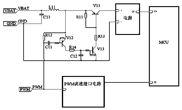
[0020] As shown in Figure 2, a low-power switching circuit for a controller based on a PWM speed regulation signal includes a differential switch circuit, an integral switch circuit, and a power switch circuit. The control terminal of the differential switch circuit is connected to the PWM speed regulation signal, and the differential switch circuit The input end of the circuit is connected to the power supply voltage VBAT, the output end of the differential switch circuit is connected to the control end of the integral switch circuit, the input end of the integral switch circuit is connected in series with the resistor R13 and the resistor R11 in sequence, and then connected to the power supply voltage VBAT, and the output end of the integral switch circuit is grounded. The control terminal of the power switch circuit is connected between the resistor R11 and the resistor R13, the input terminal of the power switch circuit is connected to the power supply voltage VBAT, and the ...

Embodiment 2

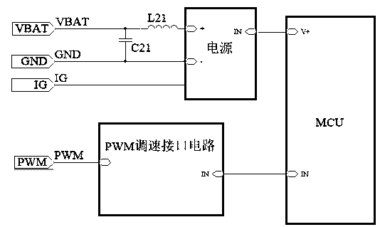
[0030] Such as figure 2 As shown, a vehicle-mounted motor controller includes a control unit, a power module and a PWM speed regulation interface circuit respectively connected to the control unit. Speed ​​regulation signal, the on-board motor controller also includes a switch circuit, the input terminal of the switch circuit is connected to the power supply voltage VBAT, the output terminal of the switch circuit is connected to the positive pole of the power module, and the control terminal of the switch circuit is connected to the PWM speed regulation signal. When there is a PWM speed control signal, switch the circuit path; when no PWM speed control signal is output, the switch circuit cuts off the line between the power supply voltage VBAT and the power module, and the control unit enters a low power consumption mode.

[0031] In the prior art, electronic components such as resistors, capacitors, and transistors can be used to build different switching circuits to realize...


PUM


Abstract

An onboard motor controller and a controller low-power switch circuit based on a PWM speed control signal relate to the field of electronic control. The onboard motor controller includes a control unit, a power module, a PWM speed control interface circuit and a switch circuit. The switch circuit includes a differential switch circuit, an integral switch circuit and a power switch circuit. The PWMspeed control signal is input into the control end of the differential switch circuit. The input end of the differential switch circuit is connected to a supply voltage VBAT. The output end of the differential switch circuit is connected to the control end of the integral switch circuit. The input end of the integral switch circuit is connected in series with a resistor R13 and a resistor R11, and then is connected to the supply voltage VBAT. The output end of the integral switch circuit is grounded. The control end of the power switch circuit is connected between the resistor R11 and the resistor R13. The input end of the power switch circuit is connected to the supply voltage VBAT. The output end of the power switch circuit is connected to the positive electrode of the power module. Theonboard motor controller is simple in structure, low in cost and good in applicability.

Description

technical field [0001] The invention relates to the technical field of electronic control, in particular to a vehicle-mounted motor controller and a low-power switch circuit of the controller based on a PWM speed regulation signal. Background technique [0002] Vehicle-mounted motor controller is a microcomputer controller dedicated to automobile motors, and is called "driving computer" or "vehicle computer". It mainly includes a control unit, a power module connected to the control unit and a PWM speed regulation interface circuit. The positive pole of the module is connected to the power supply voltage VBAT, the negative pole is grounded to GND, and the PWM speed control interface circuit is connected to the PWM speed control signal. When the car is driving, the on-board motor controller is in the working state, and when the car is suspended, in order to save energy and electricity, the driver usually puts the on-board motor controller into a low-power standby mode. At pr...

Claims


Application Information

Patent Timeline
Patent Type & Authority Applications(China)
IPC IPC(8): H02P23/00
Inventor 刘锴黄瑞文礼周莉芳
Owner ZHUZHOU ELITE ELECTRO MECHANICAL
Why Eureka
Try Eureka