Electromagnetic valve for fluid flow control

A fluid flow and solenoid valve technology, applied in the field of solenoid valves, can solve the problems of poor sealing effect and effective control of the fluid cleanliness of the solenoid valve, and achieve the effects of long service life, simple structure and guaranteed cleanliness.

Active Publication Date: 2015-11-18
ZHEJIANG KANGHE MECHANICAL ENG CO LTD
View PDF6 Cites 4 Cited by
  • Summary
  • Abstract
  • Description
  • Claims
  • Application Information

AI Technical Summary

Problems solved by technology

As a precise control element, the solenoid valve needs to act quickly and reliably, and has high requirements for the cleanliness of the fluid passing through the solenoid valve. The current public solenoid valve inlet does not effectively control the cleanliness of the fluid entering the solenoid valve.
In addition, the electromagnetic valve, as a component for controlling fluid on-off, has strict requirements on sealing effect and durability. The currently disclosed electromagnetic valves for engine braking are mostly sealed with steel balls, which have the defect of poor sealing effect.

Method used


Image

  • Electromagnetic valve for fluid flow control
  • Electromagnetic valve for fluid flow control
  • Electromagnetic valve for fluid flow control

Examples


Embodiment Construction

[0030] The present invention will be further described below with specific embodiment, see figure 1 -9:

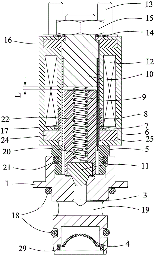
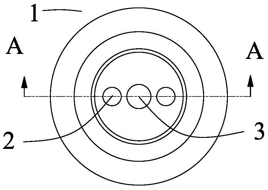
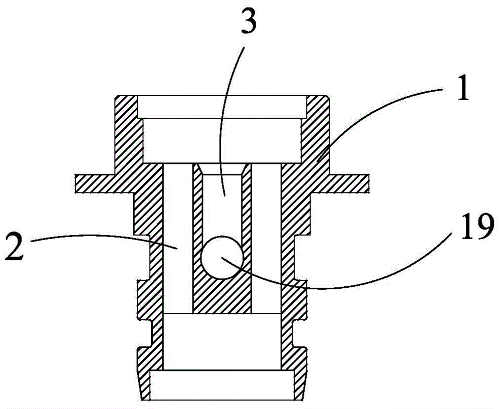
[0031] A solenoid valve for controlling fluid flow, comprising a valve body 1 , a core tube assembly 5 , and a plastic sealing assembly 6 . The valve body core pipe assembly 5 is threadedly connected to the valve body 1, and interference connection and other methods can also be used.

[0032] The core tube assembly 5 includes a core tube 7, a moving magnetic core 8 arranged in the core tube 7, a static magnetic core 10 and a return spring 9, and the upper end of the static magnetic core 10 and the core tube 7 is welded or tightly fitted. Wait. The moving magnetic core 8 is located inside the core tube 7, and the lower end is provided with a sealing plug 11 for sealing the outlet 3. The return spring 9 is located in the slot 22 inside the moving magnetic core 8, and the depth of the spring slot 22 directly runs through the entire moving magnetic core. 8 is connected with...


PUM


Abstract

The invention belongs to the field of electromagnetic control fluid, and relates to an electromagnetic valve for fluid flow control. The electromagnetic valve comprises a valve body which is provided with an inlet and an outlet. The valve body is connected with a core tube assembly which is sleeved with a plastic package assembly. The core tube assembly comprises a core tube, a movable magnetic core and a reset spring. A static magnetic core is arranged at the upper end of the core tube. The movable magnetic core is located in the core tube, and a sealing plug used for sealing the outlet of the valve body is arranged at the lower end of the core tube. The reset spring is located in a spring insertion groove in the movable magnetic core, and the upper end of the reset spring is connected with the static magnetic core in a contact mode. The two-position two-way electromagnetic valve used for controlling an engine oil line is simple in structure, and connection and disconnection of the oil line are achieved through connection and disconnection of a coil; the two-position two-way electromagnetic valve used for controlling the engine oil line is good in sealing effect through a conical seal, the two-position two-way electromagnetic valve can bear impact caused by repeated opening and closing of the electromagnetic valve, and the service life of the two-position two-way electromagnetic valve is long.

Description

Technical field: [0001] The invention belongs to the field of electromagnetic control fluid, and relates to an electromagnetic valve for controlling fluid flow. Background technique: [0002] Solenoid valves are widely used in the control of engine oil circuit systems, especially the oil circuit control of engine brakes. It is known from the prior art that solenoid valves usually include a valve body, a spool and an electromagnetic control mechanism. Axial movement in the valve body controls the opening and closing of the solenoid valve to establish fluid communication between the inlet and outlet of the solenoid valve. As a precise control element, the solenoid valve needs to act quickly and reliably, and has high requirements on the cleanliness of the fluid passing through the solenoid valve. The current open solenoid valve inlet does not effectively control the cleanliness of the fluid entering the solenoid valve. In addition, the electromagnetic valve, as an element for...

Claims


Application Information

Patent Timeline
Patent Type & Authority Applications(China)
IPC IPC(8): F16K31/06F16K1/38B01D35/04
CPCB01D35/04F16K1/385F16K31/0655
Inventor 关大众刘玉芳马国伟陈能舜袁振艺赵阔曹中基
Owner ZHEJIANG KANGHE MECHANICAL ENG CO LTD
Why Eureka
Try Eureka