Upper assembled electric ball valve

A technology for electric ball valves and top loading, which is applied in the direction of valve devices, engine components, cocks including cut-off devices, etc. It can solve the problem that it is not enough to make up for the sealing and performance defects, and the misalignment of the ball and spherical sealing rings and the rotating shaft is difficult to solve Sealing performance and other issues, to achieve a wide range of application prospects and promotion of use value, control accuracy and switch performance is stable and reliable, to ensure the effect of mechanical strength and performance

Inactive Publication Date: 2006-12-27
陈蕾
View PDF0 Cites 4 Cited by
  • Summary
  • Abstract
  • Description
  • Claims
  • Application Information

AI Technical Summary

Problems solved by technology

[0004] Valve body 4-1 → install O-ring sealing ring I4-2 along the valve body axis (the same below) → install spherical sealing ring 4-3 → install rotating shaft 4-4 and O-ring sealing ring III4 perpendicular to the valve body axis -6→Install 4-8 balls→Install spherical sealing ring 4-3 along the valve body axis (the same below)→Install O-ring I4-2→Install O-ring II4-5 and bonnet 4 -6; From the assembly of ordinary ball valves, it can be seen that there are 9 valve bodies, O-ring seals I (2 pieces), spherical seals (2 pieces), balls, O-ring seals II (2 pieces) and bonnets. The error chain and assembly chain formed by the parts are difficult to solve the contradiction between good sealing performance and as small a rotation torque as possible; moreover, higher machining accuracy requirements are put forward for ordinary ball valves, which increases the manufacturing cost
The control accuracy and performance of ordinary ball valves are the result of the superposition of machining accuracy errors and assembly accuracy errors of multiple parts. torque increase
In addition, because the assembly force of ordinary ball valves acts on the two parts of the valve body and the valve cover respectively during installation and use, it is easy to cause the connection between the valve body and the valve cover to loosen, cause leakage of the water supply pipeline, and even cause serious consequences of a large amount of water leakage. , especially in the heating central heating system, the consequences of leakage of high temperature hot water are very serious
Although ordinary ball valves use 2 pieces of O-ring I to improve the sealing and rotational torque performance caused by the error chain and assembly chain, but because the elastic deformation of O-ring I is limited, the general deformation adjustment is ≤0.3- 0.5mm, not enough to make up for the sealing and performance defects caused by the above reasons

Method used


Image

  • Upper assembled electric ball valve
  • Upper assembled electric ball valve
  • Upper assembled electric ball valve

Examples


Embodiment

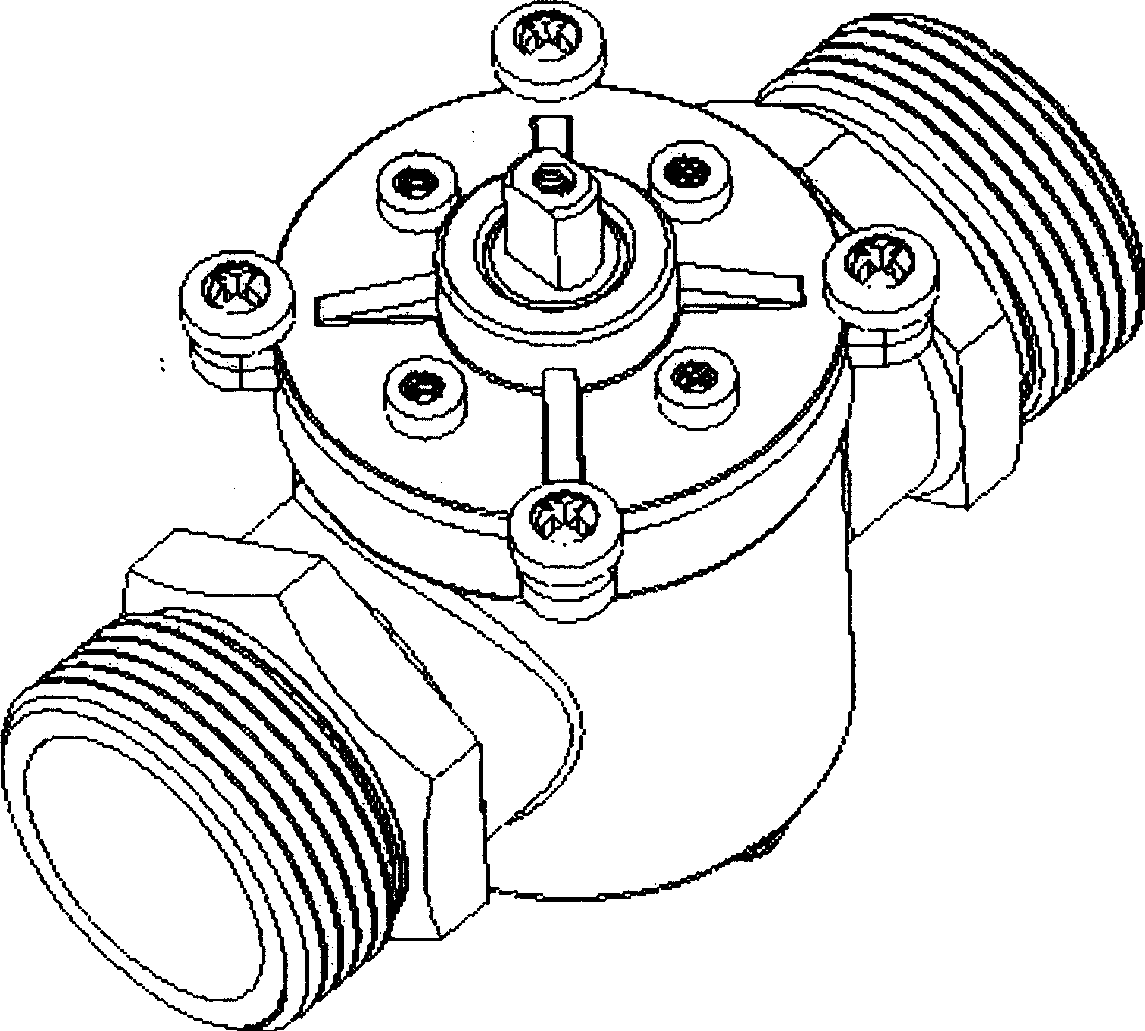
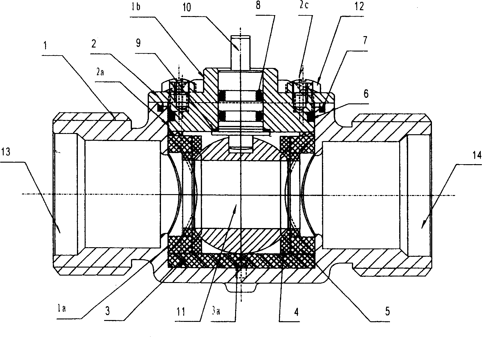
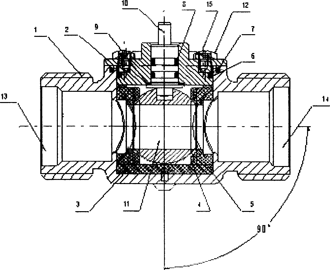
[0035] Embodiment: A convenient top-mounted electric ball valve for disassembly (see Figure 1-3 and 5), comprising a ball valve body 1, a ball valve upper cover 2, a valve core 3, a water inlet 13, a water outlet 14 and an electronic control unit, and is characterized in that a special-shaped spherical sealing ring 4, a silicon rubber elastic sealing ring are arranged in the valve core 3 5. O-shaped sealing ring I6, O-shaped sealing ring II7, O-shaped sealing ring III8, polytetrafluoroethylene wear-reducing washer 9, rotating shaft 10, sphere 11 and fastening screw 12 form a detachable ball valve core assembly. Upper cover 2, valve core 3, special-shaped spherical seal ring 4, silicone rubber elastic seal ring 5, O-ring seal I6, O-ring seal II7, O-ring seal III8, polytetrafluoroethylene anti-friction washer 9, rotating shaft 10. The assembly of the ball 11 and the fastening screw 12 is perpendicular to the axis of the water supply pipeline (see attached image 3 ), that is, ...


PUM


Abstract

The invention relates to an upper install ball valve, whose element is vertical to the water direction or the axle of water tube, wherein the invention has high control accuracy, stable property, and low rotation torque, while its idle rotation torque is not higher than 0.5N-m (0.05kgf-m); and the invention has high property than common ball valve, whose pressure resistance is improved from 1.6MPa to 3.5MPa. The inventive ball valve element is mounted on the valve body.

Description

(1) Technical field: [0001] The invention relates to a ball valve, in particular to a conveniently disassembled top-mounted electric ball valve suitable for working under high temperature, high pressure and continuous flow with bad water quality. (two) background technology: [0002] With the rapid development of my country's national economy, the demand for resources is increasing, especially in terms of water resources. my country's per capita water resources are only 2,710 cubic meters, about 1 / 4 of the world's per capita water resources, ranking 88th in the world. Some foreign countries have already adopted water recycling measures for industrial water use, and the water reuse rate is as high as 70% to 90%, while most cities in China still stay at the level of 20% to 50%. Due to the backward technology, the industrial water quota is far higher than the foreign advanced level. In order to ensure the sustainable development of my country's national economy, energy conser...

Claims


Application Information

Patent Timeline
Patent Type & Authority Applications(China)
IPC IPC(8): F16K5/06
Inventor 陈蕾
Owner 陈蕾
Why Eureka
Try Eureka