Hole machining fixture for irregular thin-wall cavity parts

An irregular hole processing technology, applied in the direction of manufacturing tools, metal processing equipment, metal processing machine parts, etc., can solve the problem that the annular thin-walled parts cannot fit with the stepped surface, the lower end surface of the annular thin-walled parts is uneven, and the annular thin-walled parts cannot be applied. Thin-walled parts, etc., to achieve a wide range of applications, ensure the tolerance of aperture size and shape and position, and reduce the rate of rejection.

Pending Publication Date: 2019-05-31
KUNSHAN JIANGJIN MACHINERY
View PDF1 Cites 9 Cited by
  • Summary
  • Abstract
  • Description
  • Claims
  • Application Information

AI Technical Summary

Problems solved by technology

[0004] The above-mentioned patents have the following problems: 1. Due to the thin wall thickness of the annular thin-walled part, deformation is prone to occur after rough machining. If the upper and lower end surfaces of the part are uneven, the lower end surface of the annular thin-walled part is directly placed on the step surface , the lower end surface of the annular thin-walled part is not flat, and the annular thin-walled part cannot fit the step surface, and subsequent processing will inevitably affect the accuracy. Therefore, the technical solution of the above-mentioned patent cannot be applied to the annular thin-walled part for hole processing; 2. The above-mentioned patent is only applicable For the ring-shaped thin-walled parts with low height, because in the technical solution of the above-mentioned patent, the pressure plate and the limit block only act on the lower part of the ring-shaped thin-walled part. If the height of the ring-shaped thin-walled part is high, there is no Restriction will cause great deformation in the middle and upper sections

Method used


Image

  • Hole machining fixture for irregular thin-wall cavity parts
  • Hole machining fixture for irregular thin-wall cavity parts
  • Hole machining fixture for irregular thin-wall cavity parts

Examples


Embodiment Construction

[0028] The specific implementation manners of the present invention will be further described below in conjunction with the drawings and examples. The following examples are only used to illustrate the technical solution of the present invention more clearly, but not to limit the protection scope of the present invention.

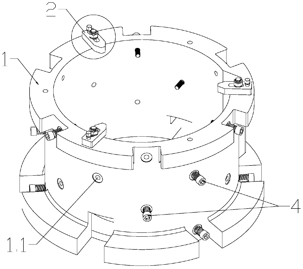
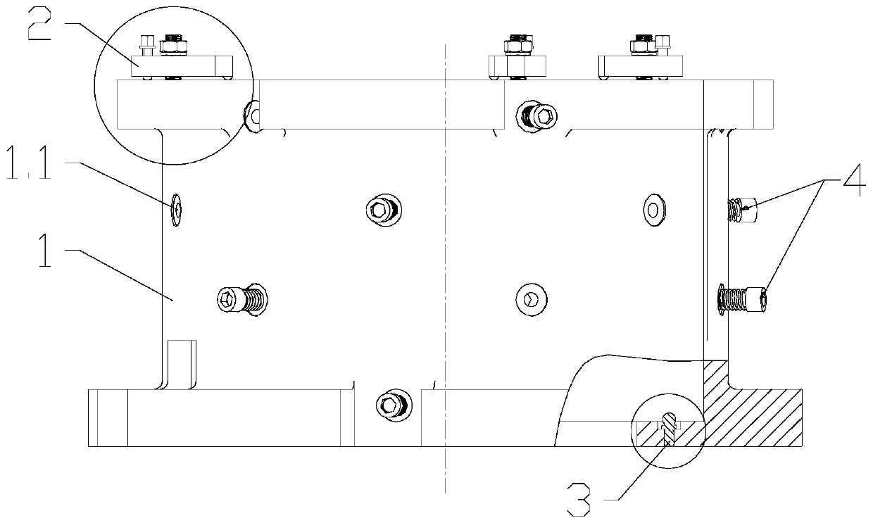
[0029] see Figure 1-6 , the present invention relates to a fixture for hole processing of irregular thin-walled cavity parts, which includes a fixture body 1, a top pressing assembly 2, a support nail 3 and a middle pressing assembly 4, and the workpiece 5 is an irregular thin-walled As for the cavity part, the workpiece 5 is placed in the cavity of the fixture body 1 .

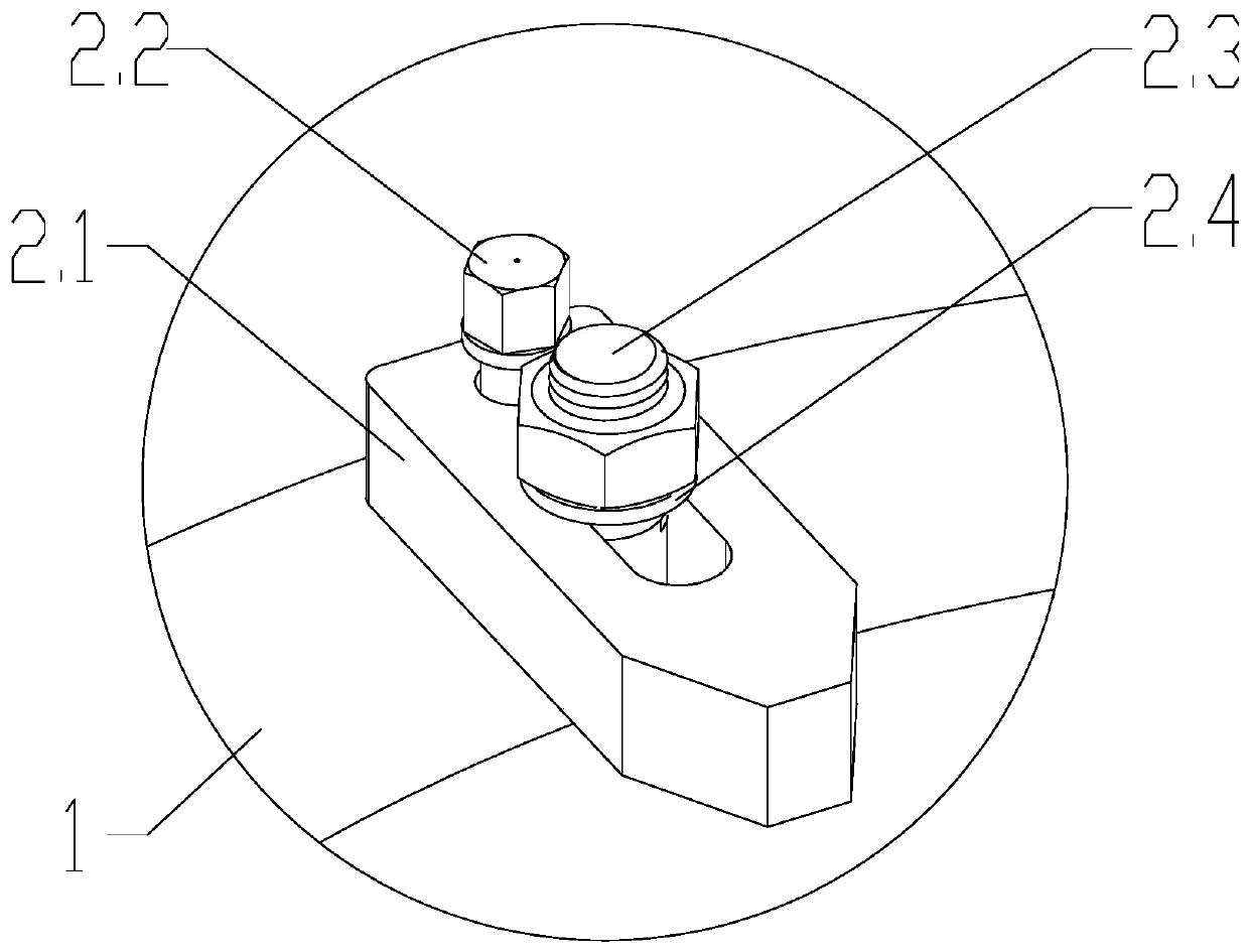
[0030] There are three top pressing components 2, which are evenly arranged on the top of the fixture body 1. The top pressing component 2 includes a pressure plate 2.1, a support screw 2.2 and a locking bolt 2.3. The outer end of the pressure plate 2.1 is against the upper surface of th...


PUM


Abstract

The invention relates to a hole machining fixture for irregular thin-wall cavity parts. The fixture comprises a fixture main body, a top pressing module, a support nail and a middle pressing module; workpieces are positioned in a cavity of the fixture main body; the top pressing module is arranged at the top of the fixture main body; the top pressing module butts against the upper end surfaces ofthe workpieces; through holes are uniformly formed in the cylindrical surface of the fixture main body; the middle pressing module penetrates through the through holes to butt against the side surfaces of the workpieces; the support nail is arranged on a base of the fixture main body; and a screw cap of the support nail butts against the bottoms of the workpieces. The hole machining fixture for the irregular thin-wall cavity parts is provided with the support nail capable of adjusting the heights of the workpieces at the bottom, is provided with the middle pressing module for centering and positioning the workpieces at the middle part, is provided with the top pressing module for axially locking the workpieces at the top, can effectively and stably control the deformation of holes, guarantees the aperture size tolerance and the form and location tolerance, achieves wide application range, and guarantees the part quality in the use process.

Description

technical field [0001] The invention relates to a fixture for hole processing of irregular thin-walled cavity parts, aimed at thin-walled cavity parts with high requirements on hole diameter tolerance or easy deformation of hole processing. It belongs to the field of mechanical technology. Background technique [0002] When processing high-precision thin-walled cavity parts (such as water jackets, shaft sleeves, etc.), due to the large amount of removal, thin wall of the workpiece, low rigidity, and the drawings require relatively high precision in the size, shape and position of the hole, during the processing The main problem to be solved is to control and reduce the deformation of parts. If there is a problem with the clamping method, it will cause the processing deformation of the part hole. Due to the stress release, the hole size is still out of tolerance, and because of the irregular shape of the part, it is difficult to find the law for the deformation and cannot co...

Claims


Application Information

Patent Timeline
Patent Type & Authority Applications(China)
IPC IPC(8): B23Q3/06
Inventor 张明红彭瑜华史兆飞刘书亮张传学
Owner KUNSHAN JIANGJIN MACHINERY
Why Eureka
Try Eureka