Contact type train obstacle detecting device and a train

A technology of obstacle detection and detection device, which is applied in the field of rail transit, can solve complex mathematical calculations, mechanical simulation, difficulties and other problems, and achieve the effects of accurate adjustment, guaranteed effect, direct and accurate detection

Pending Publication Date: 2019-05-31
浙江众合科技股份有限公司
View PDF0 Cites 0 Cited by
  • Summary
  • Abstract
  • Description
  • Claims
  • Application Information

AI Technical Summary

Problems solved by technology

The corresponding relationship between the leaf spring and the applied force requires complex mathematical calculations, mechanical simulation and experimental verification, which brings great difficulties to different models to adjust different collision forces to trigger braking.

Method used


Image

  • Contact type train obstacle detecting device and a train
  • Contact type train obstacle detecting device and a train
  • Contact type train obstacle detecting device and a train

Examples


Embodiment 1

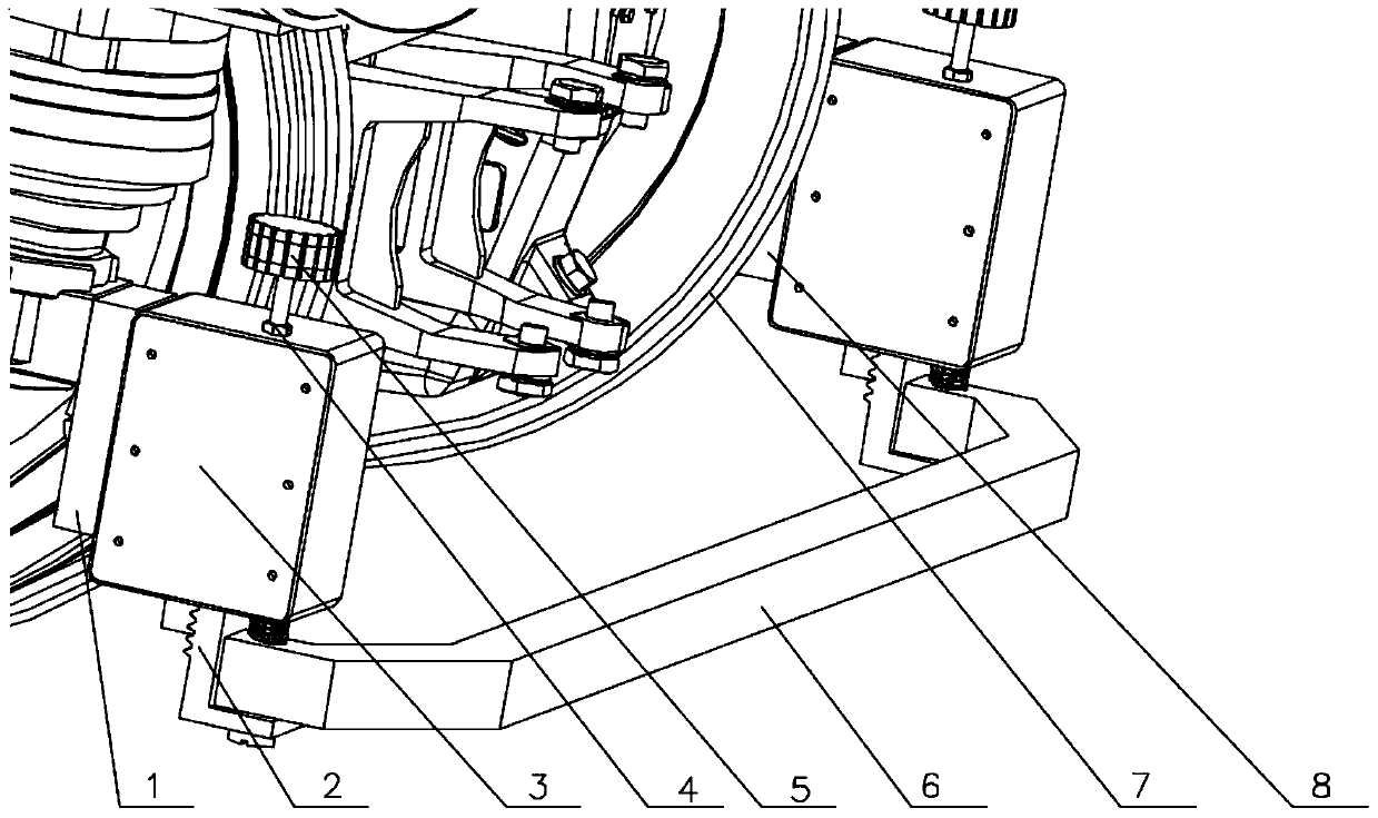
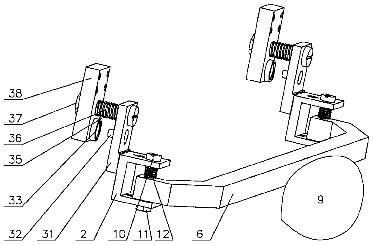
[0031] Such as Figure 1 to Figure 5 As shown, a contact type train obstacle detection device includes a detection beam 6 and a height adjustment mechanism for adjusting the height of the detection beam. The bracket 2 is provided with a linear slide rail between the height adjustment bracket 2 and the height adjustment bracket mounting part 31, and the height adjustment bracket 2 is driven to adjust the height along the linear slide rail by the driver.

[0032] Optionally, the height adjustment bracket 2 is locked by a locking structure after being adjusted in height relative to the height adjustment bracket mounting part 31, so that the height adjustment bracket 2 is fixed in height.

[0033] Wherein, the height adjustment bracket 2 is connected with an adjustment lead screw, and the adjustment lead screw is threadedly connected with the lead screw nut to form a lead screw pair. In this embodiment, the lead screw nut is arranged on the component box 3 . The adjustment screw...

Embodiment 2

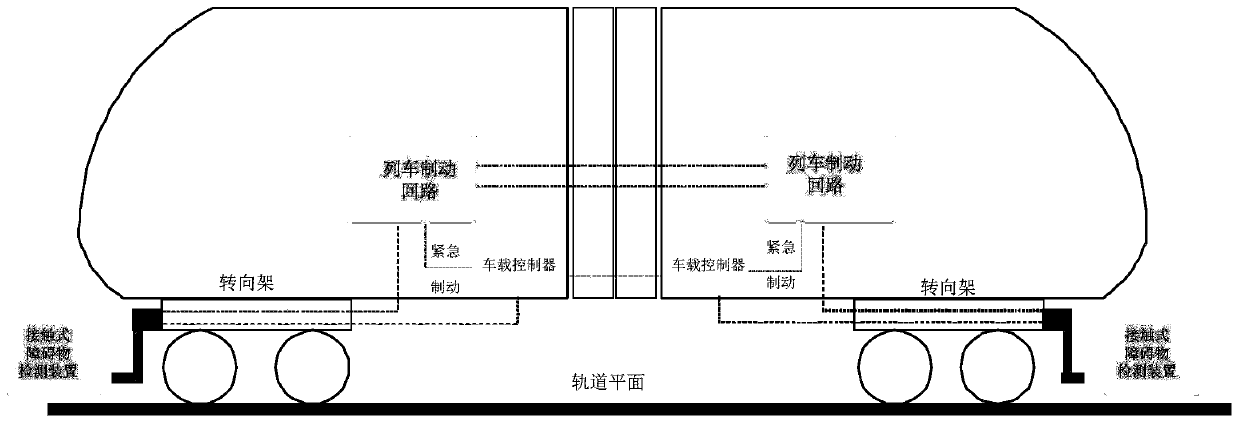
[0045] A train is equipped with the contact type train obstacle detection device in the above embodiment.

[0046] refer to figure 2 As shown, the contact train obstacle detection device communicates with the on-board controller and the brake circuit. When the detection beam hits an obstacle and the impact force generated by the obstacle exceeds the preset obstacle impact force, the electrical component box The force sensor will transmit the signal to the on-board controller of the train to inform the train of emergency braking due to obstacles, trigger the brake command of the on-board controller, and connect the signal to the brake circuit to ensure successful braking.

[0047] When the detection device detects that the impact force of the obstacle is greater than the preset value, it will trigger the braking signal, which is connected to the train braking circuit, and at the same time, the braking signal is sent to the on-board controller of the train, and the on-board con...


PUM


Abstract

The invention discloses a contact type train obstacle detecting device and a train. The contact type train obstacle detecting device comprises a detection beam, a detection device mounting plate fixedwith a vehicle and a mounting piece connected with the detection beam. The mounting piece is in elastic floating connection with the detection device mounting plate, and a force sensor configured todetect the impact of a barrier on the detection beam is arranged between the mounting piece and the detection device mounting plate. The force sensor is arranged between the mounting piece and the detection device mounting plate to detect the impact of the barrier on the detection beam to directly obtain the accurate force information, the direct action of the barrier on the detection plate is impact so as to more directly and accurately detect the barrier.

Description

technical field [0001] The invention relates to rail transit technology, in particular to a contact obstacle detection device. Background technique [0002] The existing contact obstacle detection device on the train usually adopts a detection beam transverse to the train track, and the detection beam is connected with an elastic support. When an obstacle hits the detection beam, it will cause an N-type leaf spring deformed. The deformation of the leaf spring will trigger the action of an electric switch or a travel switch to activate the emergency braking scheme of the train. [0003] The defect of the prior art solution is that the elastic element is a non-linear elastic deformation element leaf spring, and the travel switch or the proximity switch activates the method of judging whether the train is in an emergency brake by judging the deformation of the leaf spring. However, after the train encounters an obstacle, it is decided whether to brake urgently, depending on t...

Claims


Application Information

Patent Timeline
Patent Type & Authority Applications(China)
IPC IPC(8): G01L5/00G01B21/08B61C17/00
Inventor 刘丹丹凌祝军白剑祁香兵
Owner 浙江众合科技股份有限公司
Why Eureka
Try Eureka