
Oil and gas reservoir fracturing crack expansion simulation dynamic monitoring system and method

A technology for oil and gas reservoirs and dynamic monitoring, which is applied in the direction of applying stable tension/pressure to test the strength of materials. It can solve the problem that it is difficult to accurately display the torsional extension and extension of the fracture surface, the acoustic emission technology cannot accurately display the fracture surface, and special carbon fiber materials. Problems such as high cost and applicability

Active Publication Date: 2019-05-31
CHINA UNIV OF MINING & TECH
View PDF10 Cites 10 Cited by
  • Summary
  • Abstract
  • Description
  • Claims
  • Application Information

AI Technical Summary

Problems solved by technology

[0004] Acoustic emission technology and fluorescent tracer are the common methods for fracturing monitoring at present, but they have limitations: First, the positioning accuracy of acoustic emission technology is largely affected by the location and accuracy of the probe, and the acoustic emission The technology cannot accurately display the fracture surface of the fracture, and it is difficult to accurately present the complex extension and expansion phenomena such as torsion and bifurcation of the fracture surface; both, the effect of the fluorescent tracer can only be realized after the experiment is completed along the fracture. Reflects that the dynamic expansion path of the fracture during the fracturing process cannot be recorded
[0007] Although the above-mentioned patents can be used for real-time monitoring of fracture expansion experiments, they still have limitations. When the rock breaks through its strength limit and forms fractures, the fracture expansion rate may exceed the ability of CT to capture imaging, resulting in some key fracture expansion details. It is impossible to know; in addition, the preparation of special carbon fiber materials also has problems such as high cost and applicability

Method used


Image

  • Oil and gas reservoir fracturing crack expansion simulation dynamic monitoring system and method

Examples


Embodiment Construction

[0028] The present invention will be described in further detail below in conjunction with the accompanying drawings.

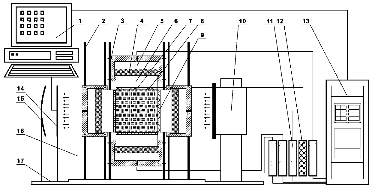
[0029] Such as figure 1 As shown, the present invention is an oil and gas reservoir fracturing expansion simulation dynamic monitoring system, including a true triaxial pressure chamber, a frame frame, a fluid injection system, a pressure loading system, a neutron photography system and a data acquisition and processing system.

[0030] The true triaxial pressure chamber is composed of six 200 mm×200 mm square aluminum alloy plates 9, including the front plate, rear plate, left side plate, right side plate, top plate and bottom plate, and the inner wall of the true triaxial pressure chamber is provided with a sealing layer The bushing 8 has a stress sensor fixed inside it. The aluminum alloy plate on the top of the true triaxial pressure chamber is provided with a fluid inlet hole 7 with a diameter of 10 mm. A cube with a size of 200 mm×200 mm×200 mm can be p...


PUM


Abstract

The invention discloses an oil and gas reservoir fracturing crack expansion simulation dynamic monitoring system and method. According to the system and method, a piston is utilized to hydraulically load a rock test piece; and the extension and expansion behavior of a fracturing crack is dynamically monitored by means of the real-time imaging function of a neutron camera system. The neutron camerasystem is introduced into a fracturing physical simulation process, and therefore, the defect that a traditional acoustic emission technology and a fluorescent tracer method fail to realize real-timemonitoring during the expansion research of a fracturing crack, and difficulty in the dynamic real-time monitoring of the extension and expansion of the fracturing crack can be eliminated, and the real-time coordination of rock true triaxial technology and neutron imaging technology is realized. The system and method are of great significance for studying the formation and extension law of the fracturing crack under a true triaxial stress state.

Description

technical field [0001] The invention relates to a dynamic monitoring system and method for simulating fracture expansion in oil and gas reservoirs, belonging to the fields of rock mechanics and oil and gas development. Background technique [0002] With the deepening of oil and gas exploration and development, conventional oil and gas resources are becoming increasingly tense, and the success of the shale gas revolution in the United States has made shale oil and gas, tight oil and gas and other unconventional oil and gas resources show strong vitality under the existing technology. my country is rich in unconventional oil and gas resources, but generally speaking, unconventional oil and gas reservoirs have the characteristics of low porosity and low permeability. Under conventional conditions, oil and gas extraction is difficult, and artificial fracturing and other technical means are needed. Mastering the law of fracture extension in oil and gas reservoirs is the key to co...

Claims


Application Information

Patent Timeline
Patent Type & Authority Applications(China)
IPC IPC(8): G01N3/12
Inventor 鞠玮申建秦勇吴财芳沈玉林
Owner CHINA UNIV OF MINING & TECH
Learn More