Camera shooting optical lens

An optical lens and lens technology, which is applied in the field of optical lens, can solve problems such as large aperture, ultra-thin wide-angle, focal power, lens distance and lens shape setting irrationality, etc., to achieve good optical performance, correction Aberration, satisfying the effect of large aperture

Active Publication Date: 2019-05-31
AAC OPTICS SOLUTIONS PTE LTD
View PDF16 Cites 37 Cited by
  • Summary
  • Abstract
  • Description
  • Claims
  • Application Information

AI Technical Summary

Problems solved by technology

However, with the development of technology and the increase of diversified needs of users, as the pixel area of ​​the photosensitive device continues to shrink, and the system’s requirements for imaging quality continue to increase, the seven-element lens structure gradually appears in the lens design. Common Although the seven-element lens already has good optical performance, its focal power, lens spacing and lens shape settings still have certain irrationality, resulting in that the camera optical lens cannot meet the requirements of large aperture while having good optical performance. , ultra-thin, wide-angle design requirements

Method used


Image

  • Camera shooting optical lens
  • Camera shooting optical lens
  • Camera shooting optical lens

Examples


no. 1 approach

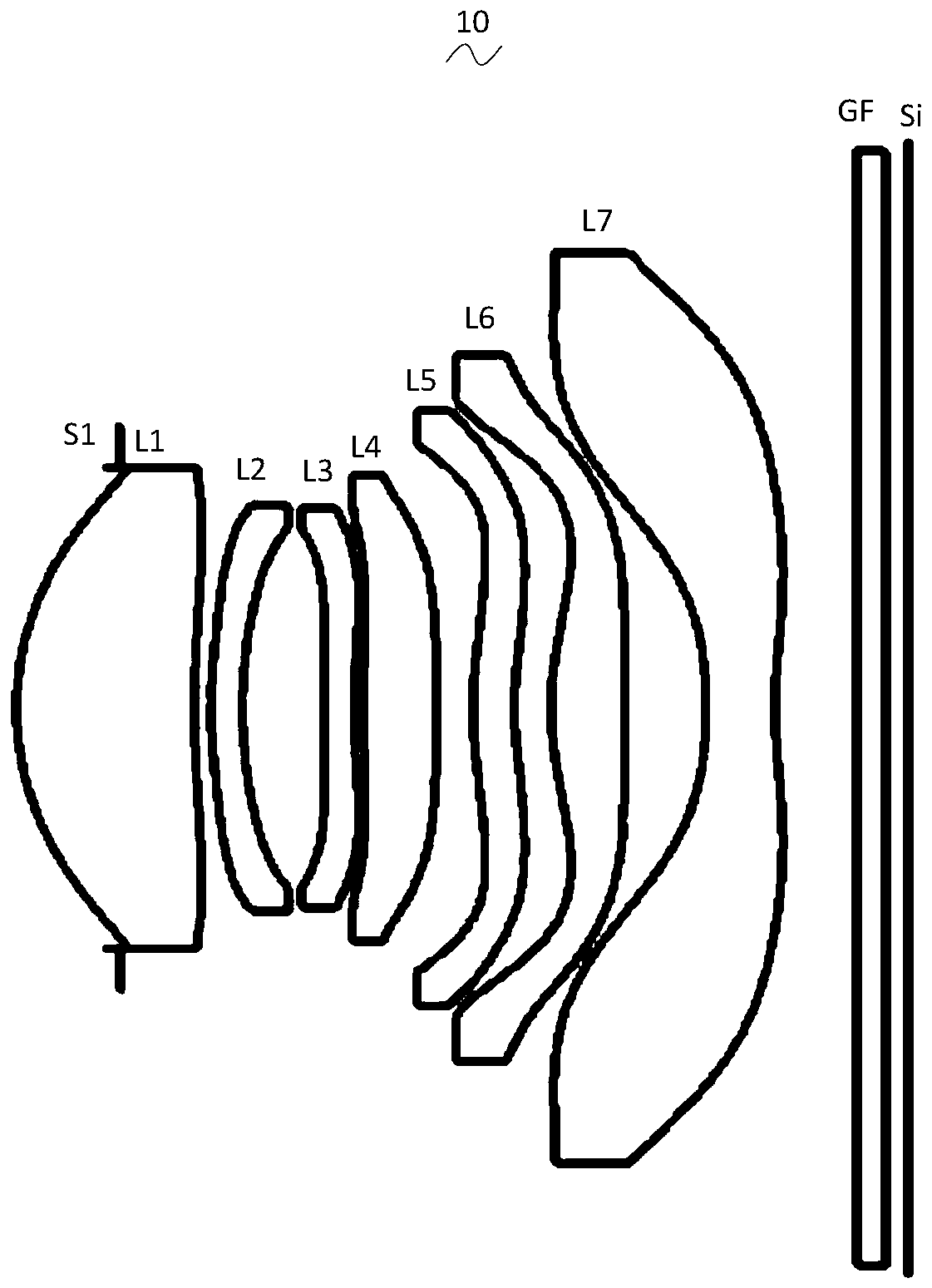
[0031] With reference to the drawings, the present invention provides an imaging optical lens 10. figure 1 Shown is the imaging optical lens 10 according to the first embodiment of the present invention. The imaging optical lens 10 includes seven lenses. Specifically, the imaging optical lens 10 includes in order from the object side to the image side: an aperture S1, a first lens L1, a second lens L2, a third lens L3, a fourth lens L4, a fifth lens L5, and a sixth lens. Lens L6 and seventh lens L7. In this embodiment, preferably, an optical element such as a glass plate GF is arranged between the seventh lens L7 and the image plane Si. The glass plate GF can be a glass cover plate or an optical filter, of course. In other embodiments, the glass plate GF can also be arranged in other positions.

[0032] In this embodiment, the first lens L1 has positive refractive power, its object side is convex outwards, and its image side is concave; the second lens L2 has negative refractive...

no. 2 approach

[0123] Figure 5 It is a schematic diagram of the structure of the imaging optical lens 20 in the second embodiment. The second embodiment is basically the same as the first embodiment, and the meaning of the symbols is the same as that of the first embodiment. Only the differences are listed below.

[0124] Table 5 and Table 6 show the design data of the camera 20 according to the second embodiment of the present invention. 【table 5】

[0125]

[0126]

[0127] 【Table 6】

[0128]

[0129] Table 7 and Table 8 show the design data of the inflection point and stagnation point of each lens in the imaging optical lens 20 of the embodiment of the present invention.

[0130] 【Table 7】

[0131]

[0132]

[0133] 【Table 8】

[0134]

[0135] In the following Table 21, the values ​​corresponding to the various parameters in the second embodiment and the parameters specified in the conditional expressions are also listed.

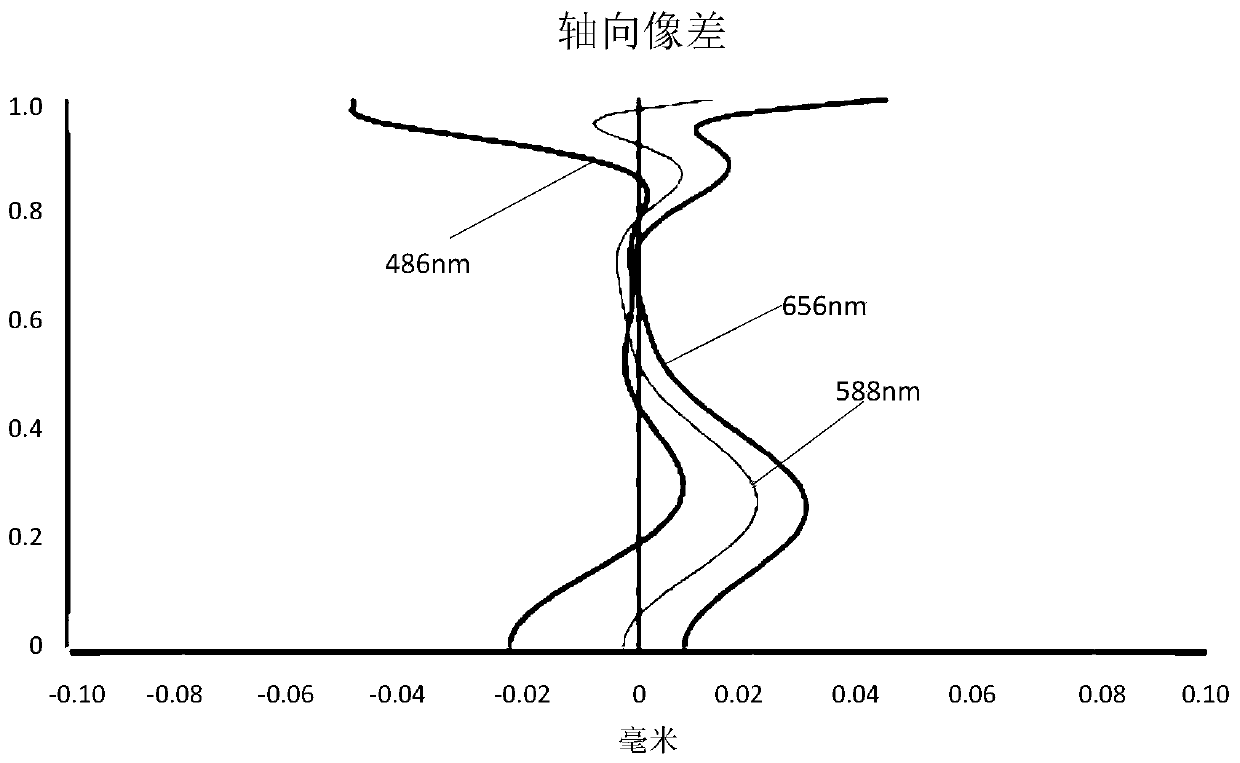
[0136] Image 6 A schematic diagram showing the axial aberration of light wi...

no. 3 approach

[0139] Picture 9 It is a schematic diagram of the structure of the imaging optical lens 30 in the third embodiment. The third embodiment is basically the same as the first embodiment, and the meaning of the symbols is the same as that of the first embodiment. Only the differences are listed below.

[0140] Table 9 and Table 10 show design data of the imaging optical lens 30 of the third embodiment of the present invention.

[0141] 【Table 9】

[0142]

[0143] 【Table 10】

[0144]

[0145]

[0146] Table 11 and Table 12 show the design data of the inflection point and stagnation point of each lens in the imaging optical lens 30 of the embodiment of the present invention.

[0147] 【Table 11】

[0148]

[0149]

[0150] 【Table 12】

[0151]

Number of stationary points

Stagnation position 1

Stagnation position 2

P1R1

P1R2

1

1.595

P2R1

P2R2

P3R1

1

0.625

P3R2

1

0.885

P4R1

2

0.765

1.705

P4R2

2

0.105

1.895

P5R1

1

1.235

P5R2

1

1.125

P6R1

1

1.275

P6R2

P7R1

1

3.095

P7R2

1

1.095

[0152] I...


PUM


Abstract

The invention relates to the field of optical lenses, and discloses a camera shooting optical lens. The lens sequentially comprises an aperture, a first lens with positive refractive power, a second lens with negative refractive power, a third lens with negative refractive power, a fourth lens with positive refractive power, a fifth lens with refractive power, a sixth lens with positive refractivepower and a seventh lens with negative refractive power from the object side to the image side. The focal length of the first lens is f1, the focal length of the second lens is f2, the axial thickness of the fourth lens is d7, the axial distance between the image side surface of the third lens and the object side surface of the fourth lens is d6, and the following relational expressions are met:-11.00<=f2/f1<=-6.00; and 5.00<=d7/d6<=10.00. The camera shooting optical lens can meet the design requirements of large aperture, ultra-thinness and wide angle while having the good optical performance.

Description

Technical field [0001] The present invention relates to the field of optical lenses, in particular to an imaging optical lens suitable for portable terminal equipment such as smart phones and digital cameras, as well as imaging devices such as monitors and PC lenses. Background technique [0002] In recent years, with the rise of smart phones, the demand for miniaturized photographic lenses has increased. The photosensitive devices of general photographic lenses are nothing more than charge coupled devices (CCD) or complementary metal oxide semiconductor devices (Complementary Metal -OxideSemicondctor Sensor, CMOS Sensor), and due to the advancement of semiconductor manufacturing technology, the pixel size of photosensitive devices has been reduced, coupled with the development trend of current electronic products with good functions, thin and short appearance, so they have good The miniaturized camera lens with image quality has become the mainstream in the current market. [000...

Claims


Application Information

Patent Timeline
Patent Type & Authority Applications(China)
IPC IPC(8): G02B13/18G02B13/06
CPCG02B13/0045G02B9/64
Inventor 卞旭琪孙雯
Owner AAC OPTICS SOLUTIONS PTE LTD
Why Eureka
Try Eureka