
Focusing system for antenna feed source

An antenna feed source and feed source technology, which is applied in the direction of antenna, antenna support/installation device, antenna grounding switch structure connection, etc., can solve the problems of increasing construction time, high weight, and prolonging construction time

Inactive Publication Date: 2019-05-31
HARBIN INST OF TECH
View PDF6 Cites 5 Cited by
  • Summary
  • Abstract
  • Description
  • Claims
  • Application Information

AI Technical Summary

Problems solved by technology

Due to the limitation of this installation method, the feed source bracket must be completely removed before each maintenance or replacement of the feed source
At the same time, because the feed source bracket of a large parabolic antenna often has a large size and high weight, it greatly increases the difficulty of maintenance and installation, increases the construction time, and increases the construction cost.
At the same time, since the feed source is fixed mechanically and does not have the ability to move, if you want to eliminate the position error caused during the installation process, the construction personnel need to repeatedly climb and debug, which increases the difficulty of construction, increases the construction risk, and prolongs the construction time.

Method used


Image

  • Focusing system for antenna feed source
  • Focusing system for antenna feed source
  • Focusing system for antenna feed source

Examples


Embodiment Construction

[0022] The following will clearly and completely describe the technical solutions in the embodiments of the present invention with reference to the drawings in the embodiments of the present invention.

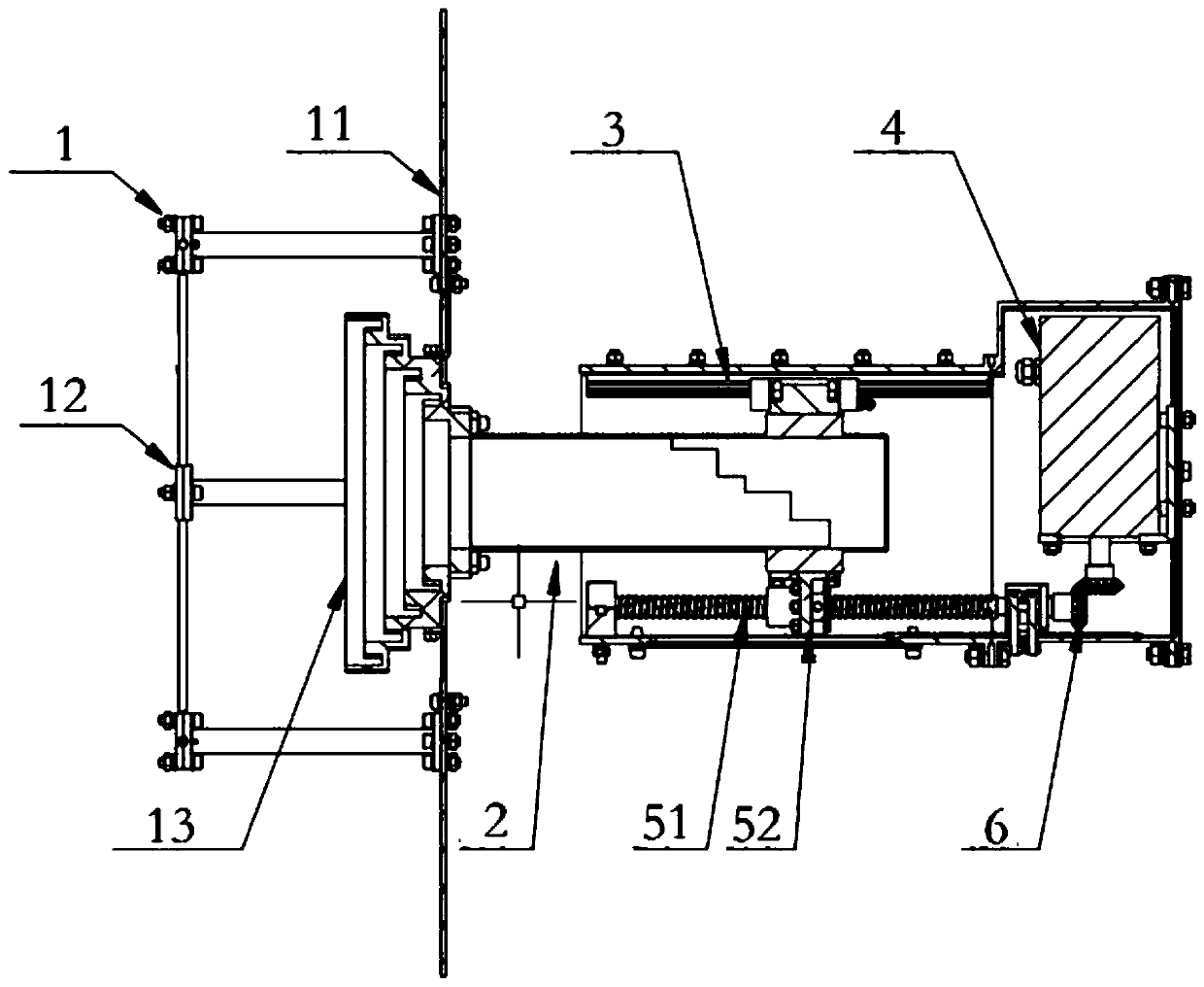
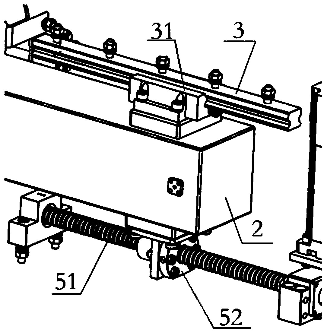
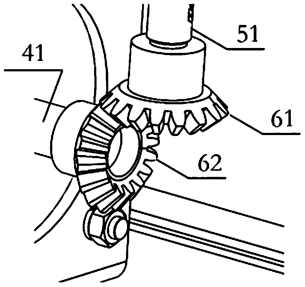
[0023] In this exemplary embodiment, a focusing system for an antenna feed is firstly provided, refer to figure 1 As shown, it mainly includes: a feed source 1, a waveguide 2, a linear guide rail 3, a lead screw 51, a driving motor 4, and the like.

[0024] Specifically, the front end of the waveguide 2 is provided with a feed source, refer to figure 1 , Figure 4 As shown, the feed source 1 includes a reflective surface 11 arranged at the front end of the waveguide 2 , and a horn feed 13 and a symmetrical oscillator feed 12 arranged on the reflective surface 11 . The feed part integrates the symmetrical vibrator array feed 12 suitable for lower frequency bands such as high frequency and very high frequency, and the horn feed source 13 suitable for higher frequency bands suc...


PUM


Abstract

The embodiment of the invention discloses a focusing system for an antenna feed source. The focusing system comprises a waveguide, wherein the front end of the waveguide is provided with a feed source, and the rear end of the waveguide is provided with a lead screw nut; a lead screw sleeved with the lead screw nut; a driving motor, wherein the output shaft of the driving motor is coupled to the lead screw for driving the lead screw; and a linear guide rail provided with a guide rail slider and connected to the waveguide. The focusing system is provided with the driving motor and the lead screw, and the lead screw nut is fixed to the rear end of the waveguide. The driving motor moves the lead screw in order that the lead screw nut moves the waveguide horizontally when moving along the horizontal direction, thereby moving the feeding source in the horizontal direction and electrically focusing the feed source. As a result, a worker can adjust the position of the feed source by controlling the drive motor on the ground.

Description

technical field [0001] The invention relates to the technical field of antennas, in particular to a focusing system for antenna feed sources. Background technique [0002] At present, most of the feedforward feed structures of large parabolic antennas are directly fixed on the feed bracket through mechanical buckles. Due to the limitation of this installation method, the feed source bracket must be completely removed before each maintenance or replacement of the feed source. At the same time, since the feed source support of a large parabolic antenna often has a large size and high weight, it greatly increases the difficulty of maintenance and installation, increases the construction time, and increases the construction cost. At the same time, since the feed source is fixed mechanically and does not have the ability to move, if you want to eliminate the position error caused during the installation process, construction personnel need to repeatedly climb and debug, which in...

Claims


Application Information

Patent Timeline
Patent Type & Authority Applications(China)
IPC IPC(8): H01Q1/12H01Q1/50H01Q19/12
Inventor 韦明川胡超然王宏旭冯田雨郭金生王峰
Owner HARBIN INST OF TECH
Learn More