Flap monitoring device

A monitoring device and skin flap technology, applied in the field of medical equipment, can solve the problems that the skin flap transplantation site cannot be irradiated by the baking lamp, the patient is easy to move unconsciously, and the recovery effect is affected, and it is convenient and fast to install, easy to operate, and reduce the overall effect of weight

Pending Publication Date: 2019-08-20
XIANGYA HOSPITAL CENT SOUTH UNIV
View PDF0 Cites 0 Cited by
  • Summary
  • Abstract
  • Description
  • Claims
  • Application Information

AI Technical Summary

Problems solved by technology

[0002] After completing the flap transplantation operation, it is necessary to keep warm the transplanted skin flap part of the patient through a baking lamp. At present, after the flap transplantation of the patient, the nurse needs to conduct intermittent ward rounds. The patient moves in a sleeping state, and it is easy for the patient to Unintentional movement prevents the skin flap from being irradiated by the oven lamp, which affects the recovery effect. This requires the nurse to manually adjust the position of the oven lamp to keep the skin flap transplanted warm and prevent the skin flap from being stimulated by the cold. The occurrence of vascular crisis, but the efficiency of this artificial postoperative ward round monitoring method is too low, and the labor load is huge

Method used


Image

  • Flap monitoring device
  • Flap monitoring device
  • Flap monitoring device

Examples


Embodiment 1

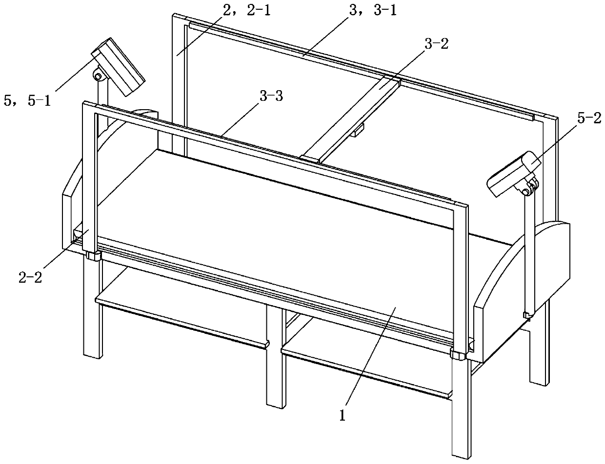
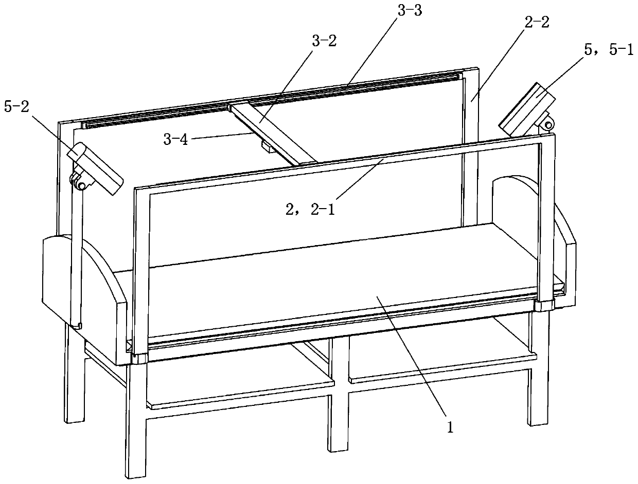
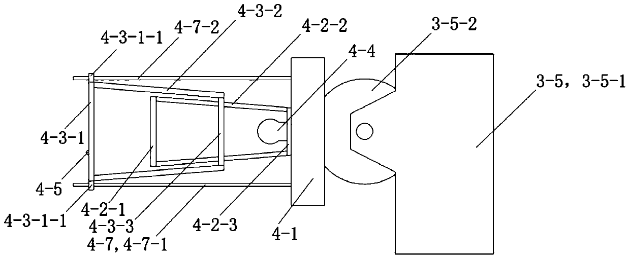
[0032] See Figure 1 to Figure 6 , the skin flap monitoring device of this embodiment includes a bed body 1, a mounting frame 2, a translation mechanism 3, a baking lamp 4, a monitoring mechanism 5, a central control terminal and a background terminal. The mounting frame 2 is arranged on the bed body 1 . The translation mechanism 3 is installed on the installation frame 2 and is located above the bed body 1 . The oven lamp 4 is installed on the translation mechanism 3 and is driven by the translation mechanism 3 to move along the length direction and the width direction of the bed body 1 . The monitoring mechanism 5 includes a front camera 5-1 and a rear camera 5-2. The front camera 5-1 and the rear camera 5-2 are respectively arranged at the bed head and the bed end of the bed body 1, and both are inclined at 45 degrees to take pictures of the bed surface. The pictures taken by the monitoring organization 5 are transmitted to the background terminal in real time through th...


PUM


Abstract

The invention discloses a flap monitoring device. The flap monitoring device comprises a bed body, a mounting frame, a translation mechanism, a heating lamp, a monitoring mechanism, a central controlterminal and a background terminal, wherein the mounting frame is arranged on the bed body; the translation mechanism is mounted on the mounting frame, and is located above the bed body; the heating lamp is mounted on the translation mechanism, and moves in the length direction and the width direction of the bed body under the driving of the translation mechanism; the monitoring mechanism comprises a front camera and a rear camera, wherein the front camera is arranged at the bed head of the bed body, and the rear camera is arranged at the bed tail of the bed body, and the front camera and therear camera are used for shooting the bed surface at the oblique angle of 45 degrees; images shot by the monitoring mechanism are transmitted to the background terminal in a real-time manner through the central control terminal, the background terminal is used for analyzing the images transmitted by the central control terminal, and giving a control command to the central control terminal according to the analysis result; and the central control terminal is used for controlling a displacement mechanism and the heating lamp according to the control command of the background terminal. Accordingto the flap monitoring device disclosed by the invention, through automatic flap monitoring, real-time monitoring and long-distance operating of the heating lamp to work are realized.

Description

technical field [0001] The invention relates to the field of medical devices, in particular to a skin flap monitoring device. Background technique [0002] After completing the flap transplantation operation, it is necessary to keep warm the transplanted skin flap part of the patient through a baking lamp. At present, after the flap transplantation of the patient, the nurse needs to conduct intermittent ward rounds. The patient moves in a sleeping state, and it is easy for the patient to Unintentional movement prevents the skin flap from being irradiated by the oven lamp, which affects the recovery effect. This requires the nurse to manually adjust the position of the oven lamp to keep the skin flap transplanted warm and prevent the skin flap from being stimulated by the cold. The occurrence of vascular crisis, but the efficiency of this artificial postoperative ward round monitoring method is too low, and the workload is huge. Contents of the invention [0003] The purpo...

Claims


Application Information

Patent Timeline
IPC IPC(8): A61N5/06H04N7/18H04N5/232
CPCA61N5/0616A61N5/0625H04N7/181A61N2005/0626A61N2005/0632A61N2005/0654A61N2005/0664H04N23/60
Inventor 彭伶丽唐举玉吴攀峰黄女桐周征兵刘明明
Owner XIANGYA HOSPITAL CENT SOUTH UNIV
Why Eureka
Try Eureka