Spiral detaching drawing device

A technology of pulling device and unscrewing seat, which is applied in the directions of hand-held tools, manufacturing tools, and solid waste removal, etc. Reliable and stable effect during unloading and drawing

Active Publication Date: 2019-06-04
ARMY ENG UNIV OF PLA
View PDF8 Cites 2 Cited by
  • Summary
  • Abstract
  • Description
  • Claims
  • Application Information

AI Technical Summary

Problems solved by technology

[0004] The purpose of the present invention is to provide a spinning and pulling device, aiming to solve the technical problems in the prior art that the head of the dangerous goods component cannot be stably unscrewed and the head cannot be pulled

Method used


Image

  • Spiral detaching drawing device
  • Spiral detaching drawing device
  • Spiral detaching drawing device

Examples


Embodiment Construction

[0040] In order to make the technical problems, technical solutions and beneficial effects to be solved by the present invention clearer, the present invention will be further described in detail below in conjunction with the accompanying drawings and embodiments. It should be understood that the specific embodiments described here are only used to explain the present invention, not to limit the present invention.

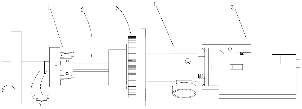
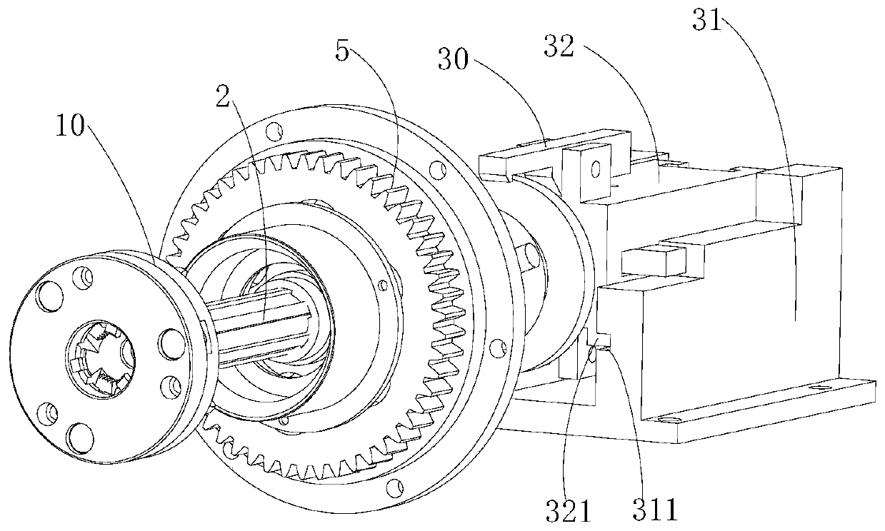
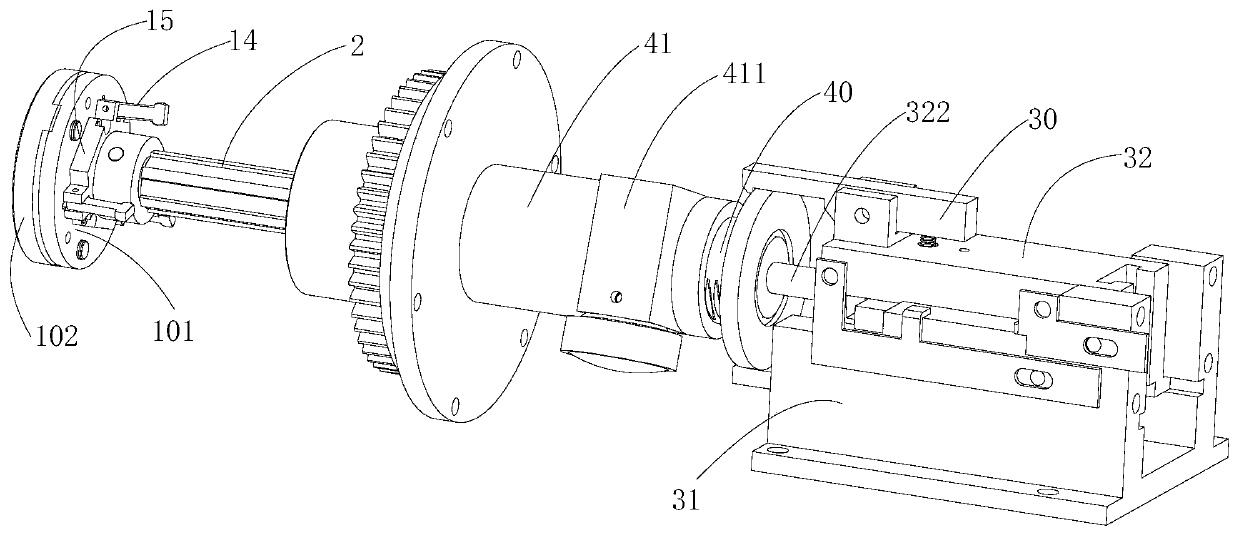
[0041] Please also refer to Figure 1 to Figure 4 , the unscrewing and pulling device provided by the present invention will now be described. The unscrewing and pulling device is used to remove the member 7 that is threadedly connected between the head 70 and the main body 71 , and includes a clamping table 6 , a unscrewing mechanism 1 , a pulling mechanism 3 and a main shaft 2 .

[0042] The clamping table 6 is used to clamp the main body 71 of the member 7 . The unscrewing mechanism 1 is located on one side of the clamping table 6, and includes a unscrewing se...


PUM


Abstract

The invention provides a spiral detaching drawing device. The spiral detaching drawing device is used for detaching a component with a head part and a main body connected in a threaded mode. The spiral detaching drawing device comprises a clamping working platform, a spiral detaching mechanism, pressing springs, a main shaft and a drawing mechanism; the spiral detaching mechanism comprises a spiral detaching seat located on one side of the clamping working platform and a plurality of clamping jaws arranged in the spiral detaching seta; the pressing springs are arranged between the clamping jaws and the spiral detaching seat; one end of the main shaft is connected with the spiral detaching seat, and the main shaft is connected with a rotating power mechanism; and the drawing mechanism comprises a plurality of drawing jaws connected with the other end of the main shaft and a straight line power mechanism connected with the drawing jaws. According to the spiral detaching drawing device, the clamping working platform is used for clamping the main body, the clamping jaws are used for clamping the head part, and the main shaft is driven by the rotating power mechanism and can drive the spiral detaching seat and the clamping jaws to rotate to enable the head part to be screwed out from the main body; the drawing jaws are driven by the straight line power mechanism, can pull the main shaft to axially move and drive the spiral detaching seat and the clamping jaws to move and finally enable the head part to be separated from the main body; and in the detaching process, the clamping jaws always clamp the head part and limit the radial movement of the head part, and the detaching process is reliable and stable.

Description

technical field [0001] The invention belongs to the technical field of dismantling equipment, and more specifically relates to a unscrewing and pulling device. Background technique [0002] Under the new international situation, the disposal of dangerous goods has become an important issue. In the task of disposing of expired stored dangerous goods components, a large number of heads that are combined with the main body in the form of threads need to be unscrewed and dismantled. This is a very dangerous process. How to change the head removal mode from manual and semi-mechanical to fully mechanical automatic processing as soon as possible, so that the processing process is safe and thorough without leaving hidden dangers, efficient and environmentally friendly, and improves efficiency. At the same time, it also relieves operators from heavy physical labor Getting rid of it is an urgent and important task for the destruction and disposal of waste dangerous goods components. ...

Claims


Application Information

Patent Timeline
IPC IPC(8): B25B27/02B09B3/00
Inventor 唐香珺韩凯任国全邵新杰赵芳曹凤利周景涛刘金华
Owner ARMY ENG UNIV OF PLA
Why Eureka
Try Eureka