Heating device and heating method

A technology of heating device and heating method, applied in the direction of combustion method, lighting and heating equipment, burner safety device, etc., to achieve high efficiency

Active Publication Date: 2019-10-11
JFE STEEL CORP
View PDF8 Cites 0 Cited by
  • Summary
  • Abstract
  • Description
  • Claims
  • Application Information

AI Technical Summary

Problems solved by technology

However, even the burner proposed in Patent Document 1 cannot be said to be sufficient in terms of the above-mentioned improvement in the ejection speed. In order to improve the heating efficiency, it is required to develop a burner capable of stably operating at a higher ejection speed. The heating device of the burner used

Method used


Image

  • Heating device and heating method
  • Heating device and heating method
  • Heating device and heating method

Examples


Embodiment 1

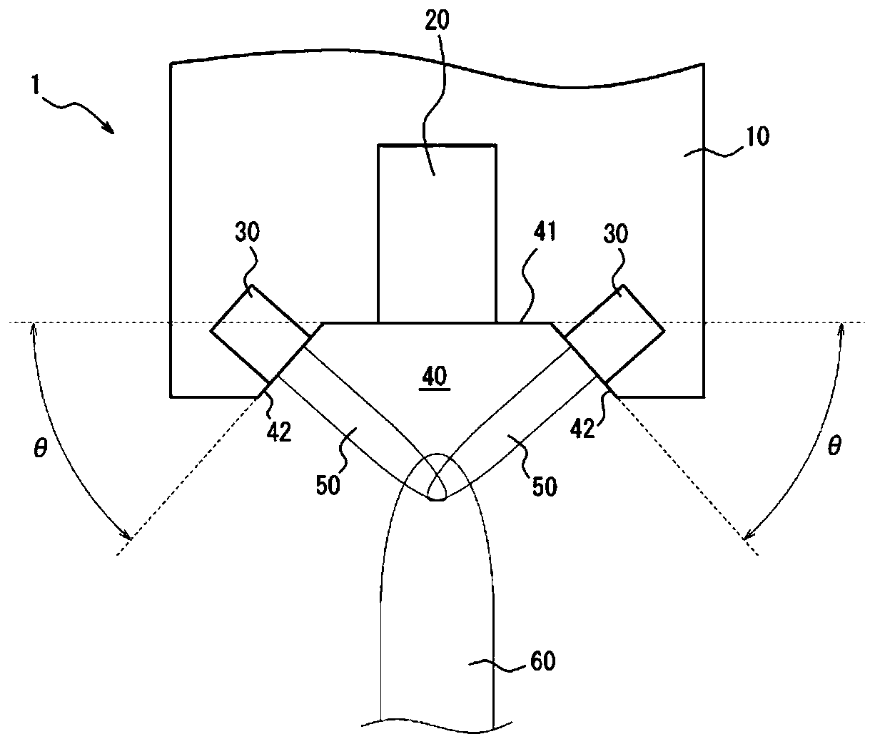
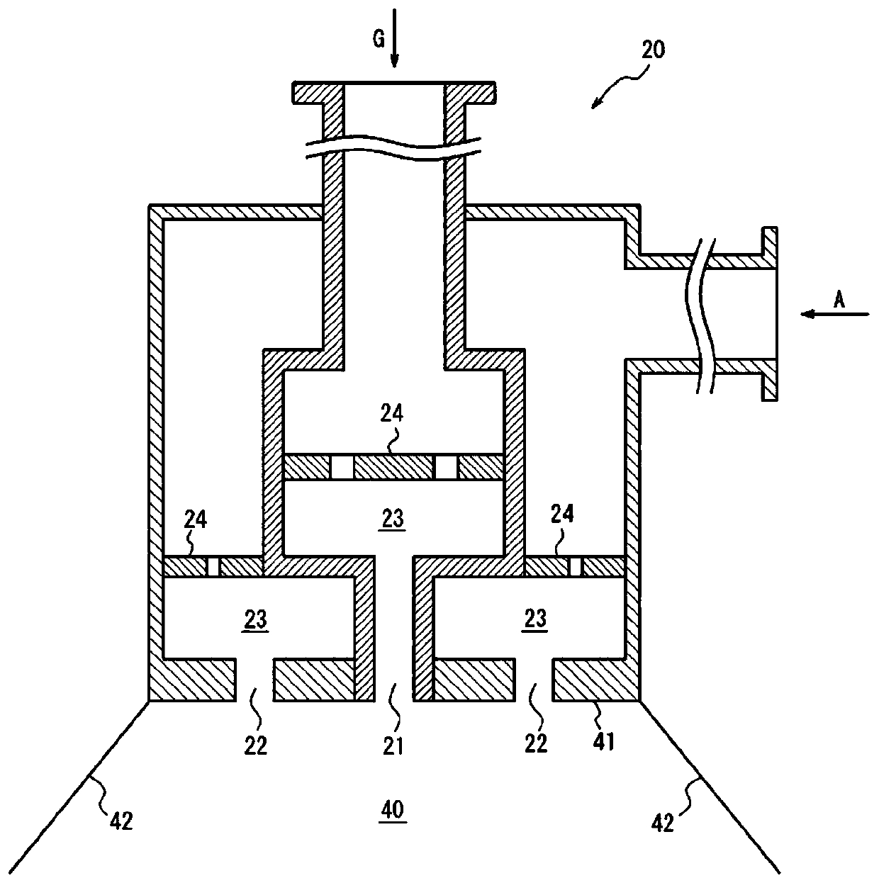
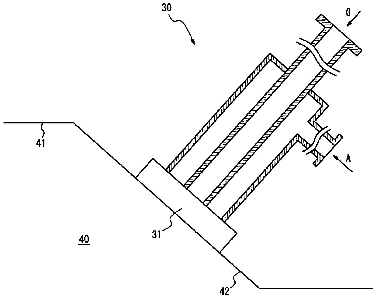
[0077] (Example 1) Figure 1 ~ Figure 3 Burner of construction shown

[0078] In above-mentioned embodiment and comparative example, with figure 1 , 8 The width of the burner in the direction perpendicular to the section shown by etc. is set to 1m. In Table 1, the size of the nozzle and the cross-sectional area of ​​the discharge part are shown. In addition, Table 1 shows the ratio of the flow rate of the fuel gas in the main burner unit to the flow rate of the fuel gas in the pilot burner unit (fuel gas flow rate ratio) in Comparative Example 2 and Example 1 together.

[0079] In Comparative Example 1, a Figure 8 The cross-sectional shape shown is a slit-shaped nozzle with a nozzle width of 10 mm and a length of 1 m. In Comparative Example 2, the one of Patent Document 1, in which 60 sets are arranged linearly between 1 m in the width direction of the burner, was used. figure 1 Nozzle as documented. Since the burner described in Patent Document 1 includes two fuel ga...


PUM


Abstract

Provided is a heating device with which it is possible to maintain a flame in a stable manner without flameout even at high discharge speeds, and to carry out heating with extremely high efficiency. Aheating device provided with a burner, wherein the burner comprises: a main burner part provided with a fuel gas nozzle for discharging a fuel gas and an air nozzle for discharging air for combustion; and a pilot burner part for combusting the fuel gas discharged from the main burner part, the pilot burner part being positioned further outward than the main burner part.

Description

technical field [0001] The present invention relates to a heating device equipped with a burner, and in particular, to a heating device capable of maintaining a flame stably without extinguishing the flame even at a relatively high ejection speed and capable of heating with extremely high efficiency. Moreover, this invention relates to the heating method using the said heating apparatus. Background technique [0002] As methods for heating articles, various methods such as hot air heating, infrared heating, heating with an electric heater, and induction heating are known. Among them, heating with a burner is widely used in various applications. [0003] Figure 8 It is a schematic diagram showing an example of a conventionally used premix burner. In the premix burner 100, combustible fuel gas 101 and air 102 are premixed inside the premix burner 100 to form a mixed gas, and the mixed gas is ejected from the premix burner 100 and burned to form Flame103. [0004] In the ca...

Claims


Application Information

Patent Timeline
Patent Type & Authority Applications(China)
IPC IPC(8): F23Q9/00F23D14/22F23D14/74F23Q9/02
CPCF23D14/22F23D14/74F23Q9/00F23Q9/045F23Q9/08F23Q9/02F23D2209/20
Inventor 堀川透理原一晃岩田好司
Owner JFE STEEL CORP
Why Eureka
Try Eureka