
LED lamp

A technology of LED lamps and wicks, applied in the field of lighting, can solve the problems of reduced service life of LED lamps, slow heat conduction rate, weak light, etc., and achieve the effect of increased refraction angle and soft light

Pending Publication Date: 2019-06-04
杭州临安天豪照明电器有限公司
View PDF9 Cites 0 Cited by
  • Summary
  • Abstract
  • Description
  • Claims
  • Application Information

AI Technical Summary

Problems solved by technology

The structure of existing LED lamps is usually that the substrate loaded with LED chips is vertically accommodated in the lamp tube, for example, the application number is "a LED fluorescent lamp" with the application number CN201310495383.X, and the wick is only distributed in the straight tube of the U-shaped tube. Because the light emitting angle of the LED chip is small, less light enters the curved tube of the U-shaped lamp (only some reflected light), so that the light at the bottom of the U-shaped lamp is weaker to form a weak light area, that is, Say, the bottom of the U-shaped light tube forms a dark area of ​​light
In addition, there are a large number of LED chips on the substrate, so the LED chips generate a lot of heat, and there is an air layer between the substrate and the U-shaped tube wall, and the heat on the LED chips is transferred to the entire U-shaped tube through the air in the U-shaped tube. U-shaped tube wall, and due to the slow heat conduction rate of air, a large amount of heat is stored in the U-shaped tube, which leads to excessive heat in the entire U-shaped tube wall, affecting the normal use of LEDs, resulting in reduced service life of LED lamps

Method used


Image

  • LED lamp
  • LED lamp
  • LED lamp

Examples


Embodiment Construction

[0022] The present invention will be further described below with reference to the accompanying drawings and specific embodiments. It should be noted that, on the premise of no conflict, the embodiments or technical features described below can be combined arbitrarily to form new embodiments. .

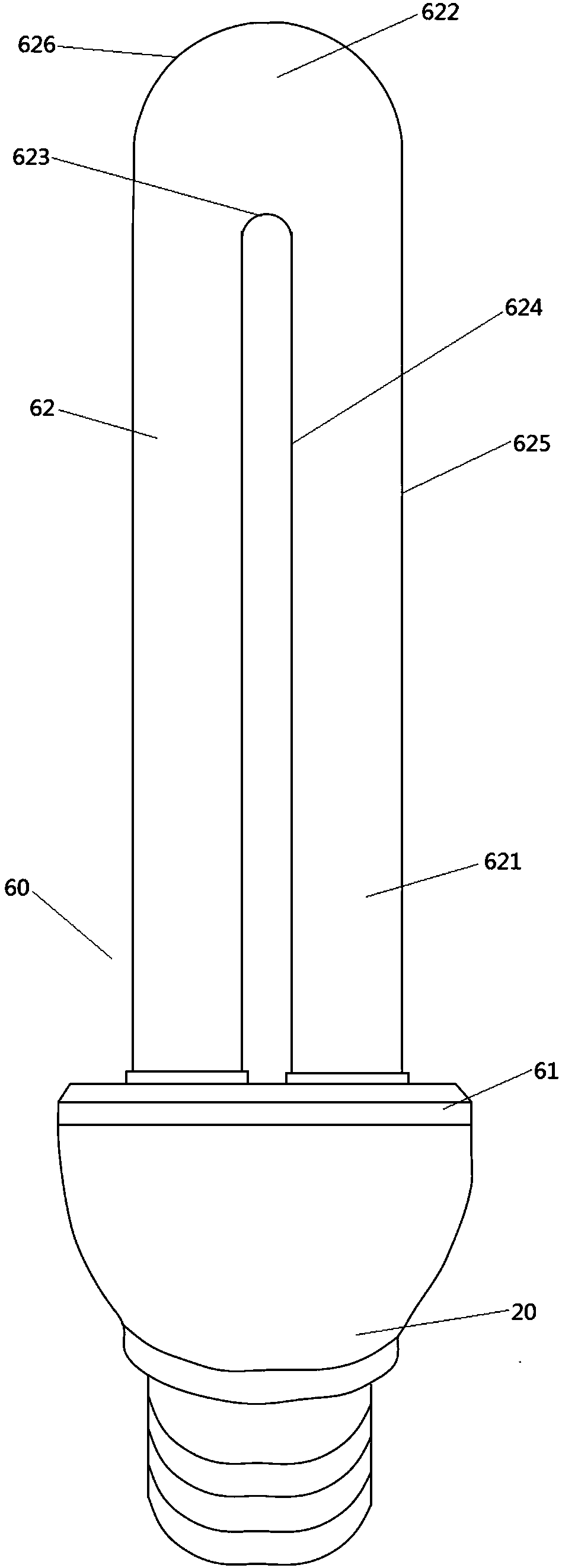
[0023] refer to figure 1 and figure 2 , the present invention provides an LED lamp, comprising a lamp cap 20, a lamp wick 40, a control circuit board and a lamp shade 60 detachably connected to the lamp cap 20, wherein the lamp shade 60 includes a connection end 61 connected with the lamp cap 20 and a connection end 61. At least one U-shaped tube 62, and each U-shaped tube 62 includes a straight tube portion 621 and a curved tube portion 622 connecting the straight tube portions 621 on both sides, the U-shaped tube 62 is in fluid communication with the lamp cap 20 and forms an accommodating space, and the wick 40 accommodates In the accommodating space, one end of the control circu...


PUM


Abstract

The invention provides an LED lamp, which comprises a lamp head, a lampwick, a control circuit board and a lampshade, wherein the lampshade is detachably connected with the lamp head, and comprises aconnecting end connected with the lamp head and at least one U-shaped pipe connected with the connecting end; the U-shaped pipe comprises a bent pipe part and straight pipe parts positioned at the twosides of the bent pipe part; the lampwick comprises at least two separated base strips; each base strip is accommodated in a pipe positioned at one side of the U-shaped pipe; each base strip has a flat straight part and a bending part; the flat straight part is accommodated in the straight pipe part; and the bending part is accommodated in the bent pipe part and is attached to the inner side pipewall of the bent pipe part. The invention aims at providing the LED lamp capable of generating soft and uniform light rays.

Description

technical field [0001] The invention relates to the technical field of lighting, in particular to an LED lamp. Background technique [0002] As a new type of light source, LED lamps are increasingly widely used with the characteristics of energy saving, environmental protection, long life and small size. The structure of the existing LED lamps is usually that the substrate loaded with LED chips is upright accommodated in the lamp tube, for example, the application number is CN201310495383.X "An LED fluorescent lamp", the wick is only distributed in the straight tube of the U-shaped tube. Due to the small light-emitting angle of the LED chip, there is less light entering the curved tube part of the U-shaped lamp (only some reflected light), so that the bottom of the U-shaped lamp is weaker to form a weak light area, that is Said, the bottom of the U-shaped tube forms a dark area of ​​light. In addition, there are a large number of LED chips on the substrate, so the LED chip...

Claims


Application Information

Patent Timeline
Patent Type & Authority Applications(China)
IPC IPC(8): F21K9/23F21V19/00F21V23/00F21V29/503F21Y115/10
Inventor 金国忠
Owner 杭州临安天豪照明电器有限公司
Learn More