
camera device

一种摄像装置、外装部件的技术,应用在冷却/通风/加热改造、仪器、通过传导传热进行修饰等方向,能够解决混入无用信号等问题,达到抑制阻碍、高效释放、简单构造的效果

Inactive Publication Date: 2021-07-02
OM DIGITAL SOLUTIONS CORP
View PDF5 Cites 0 Cited by
  • Summary
  • Abstract
  • Description
  • Claims
  • Application Information

AI Technical Summary

Problems solved by technology

For example, when the temperature inside the housing of an imaging device etc. rises, there arises a problem that an unnecessary signal (noise) is mixed into the image signal output from the imaging element etc.
Therefore, there is a problem that it is difficult to efficiently dissipate heat with this structure.

Method used


Image

  • camera device
  • camera device
  • camera device

Examples


Embodiment approach

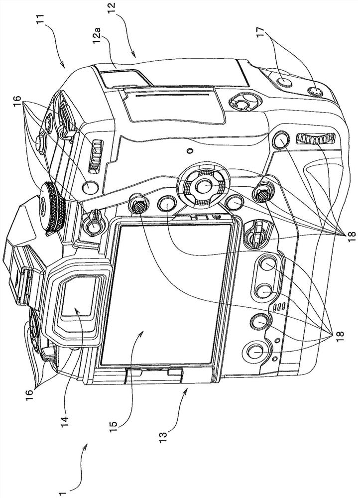
[0024] In one embodiment of the present invention, as an imaging device to which the present invention is applied, for example, the following imaging device is exemplified. The signal is recorded in a storage medium as digital data representing a still image or a moving image, and based on the image based on the image signal or digital image data recorded in the storage medium, the still image or moving image is reproduced and displayed on a display device .

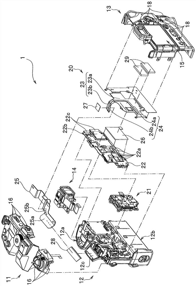
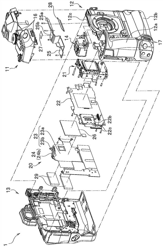
[0025] figure 1 It is an external perspective view mainly showing the back side of the imaging device according to one embodiment of the present invention. figure 2 , image 3 It is an exploded perspective view of an imaging device according to an embodiment of the present invention. in, figure 2 It is an exploded perspective view viewed from the rear side of the imaging device. image 3 It is an exploded perspective view viewed from the front side of the imaging device. Figure 4 It is a diagram showing the arra...


PUM


Abstract

The imaging device has: an electric element (22a), which generates heat; an electric substrate (22), on which the electric element is installed; a first board member (23), which is arranged in parallel with the electric substrate and opposite to the electric element. The position has a first plane part (23a) parallel to the electric substrate and a second plane part (23b) bent relative to the first plane part and arranged on the upper side of the first plane part; the first heat conduction member (26 ), which is closely arranged between the electrical component and the first plate member; a rod-shaped heat pipe (24), which has an end portion (24a) for heat absorption at one end and an end portion (24b) for heat dissipation at the other end, The heat pipe (24) is fixed on the second surface of the first plate member, the end portion for heat absorption is provided on the second surface near the electrical component, and the end portion for heat dissipation is provided on the second plane portion of the first plate member.

Description

technical field [0001] The present invention relates to an imaging device having a structure in which heat generated inside the device is released using a heat pipe. Background technique [0002] In recent years, an imaging device that converts an optical image of a subject formed by an optical lens into an image signal by using electrical components such as an imaging element and converts the image data thus obtained has been generally put into practical use and widely spread. Handling of electronic equipment. [0003] Conventional electronic equipment such as such an imaging device is generally configured by having an electric board on which a plurality of electric components are mounted inside the device casing. [0004] In this case, it is known that among the plurality of electrical components described above, there are electrical components that generate heat due to the operation of the device. [0005] Furthermore, the heat generated from these electrical components...

Claims


Application Information

Patent Timeline
Patent Type & Authority Patents(China)
IPC IPC(8): G03B17/55
CPCG03B17/02G03B17/55H05K7/2039
Inventor 镰田竜二
Owner OM DIGITAL SOLUTIONS CORP
Features
  • Generate Ideas
  • Intellectual Property
  • Life Sciences
  • Materials
  • Tech Scout
  • Unparalleled Data Quality
  • Higher Quality Content
  • 60% Fewer Hallucinations
Learn More