
Solenoid valve having adjustable spring force

A solenoid valve and valve sealing technology, which is applied in the field of solenoid valves with adjustable elastic force, can solve the problems of bolt tilt, high cost, troublesome bolt installation, etc., and achieve increased surface pressure, simple assembly, and long-lasting force transmission Effect

Active Publication Date: 2019-06-04
ROBERT BOSCH GMBH
View PDF9 Cites 1 Cited by
  • Summary
  • Abstract
  • Description
  • Claims
  • Application Information

AI Technical Summary

Problems solved by technology

However, the insertion of the bolt is relatively cumbersome and costly, for example a directional assembly is required, and in addition tilting of the bolt can occur when the bolt is fitted into the axial passage

Method used


Image

  • Solenoid valve having adjustable spring force
  • Solenoid valve having adjustable spring force

Examples


Embodiment Construction

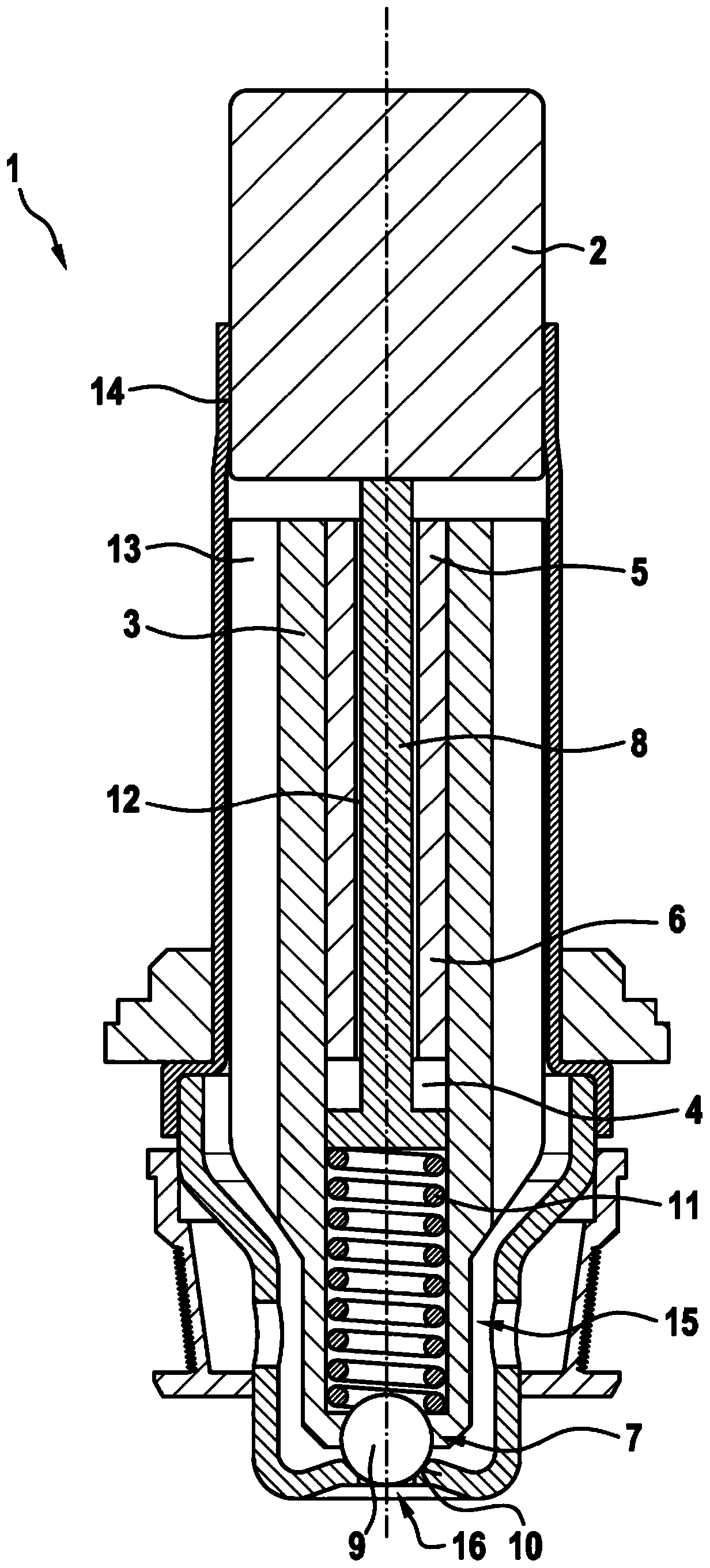
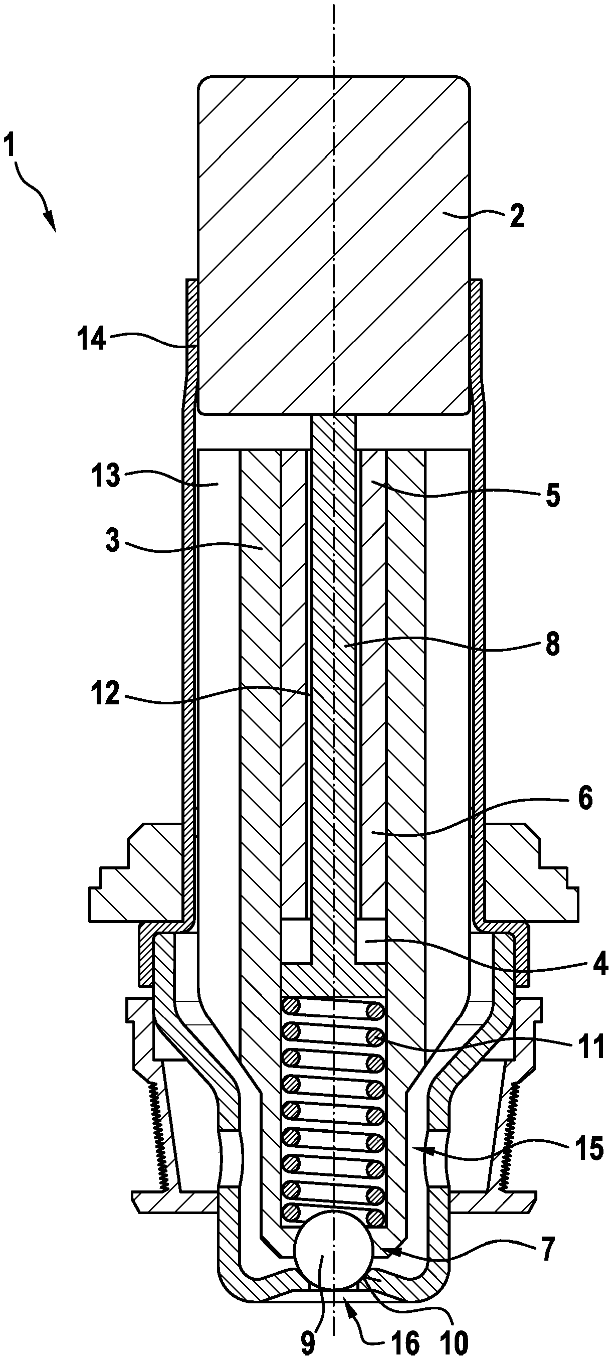
[0034] figure 1 A solenoid valve 1 for a brake system of a motor vehicle is shown in longitudinal section. The solenoid valve 1 comprises a housing 14 which is designed as a cylindrical sleeve and in which a likewise cylindrical armature 3 is arranged longitudinally or axially displaceable. Assigned to the upper end of the armature 3 is the pole core 2 connected in series or arranged with the armature 3 and locked in the housing 14 , for example by means of a welded connection. A valve body 15 held by a housing 14 and having a throughflow opening 16 is assigned to the opposite lower end of the armature 3 . Furthermore, the valve body 15 is provided with a sealing seat 10 .

[0035] The armature 3 has an axial receptacle in the form of an axial passage 4 which extends centrally through the armature 3 . The axial passage 4 is tapered towards the lower end of the armature 3 so that the armature has a radially inwardly protruding projection 7 . A three-dimensional convex objec...


PUM


Abstract

The invention relates to a solenoid valve, in particular for controlling a brake pressure of a wheel brake of a motor vehicle, comprising an axially moveably mounted armature, wherein one end of the armature is associated with a pole core and a valve sealing element is arranged at another end of the armature, wherein the armature has an axial through-opening, wherein a closure element is force-lockingly and / or interlockingly retained in the axial through-opening in a selectable position, and a plunger is axially moveably mounted in the axial through-opening, which provides a connection to thepole core in an installation position, wherein a pressure spring is positioned in the axial through-opening, wherein the pressure spring is retained in a pretensioned manner between the plunger and the closure element, characterised in that the closure element is designed as a three-dimensionally convex element.

Description

technical field [0001] The invention relates to a solenoid valve, in particular for controlling the brake pressure of wheel brakes of a motor vehicle, which has an armature mounted so that it can displace in the axial direction, wherein one end of the armature is assigned to a pole core and A valve sealing element is arranged at the other end of the armature, wherein the armature has an axial passage, wherein the blocking element is held in a non-positive and / or form-fitting manner in selectable positions in the axial passage, and the shaft A tappet is mounted axially displaceably into the passage, which is connected to the pole core in the installed position, wherein a compression spring is positioned in the axial passage, wherein the compression spring is held prestressed on the tappet and the blocking element, wherein the solenoid valve is characterized in that the blocking element is configured as a three-dimensional convex object. Background technique [0002] Solenoid...

Claims


Application Information

Patent Timeline
Patent Type & Authority Applications(China)
IPC IPC(8): B60T8/36F16K31/06
CPCB60T8/363F16K31/0665B60Y2400/81B60T15/025F16K31/10F16K31/0693F16K31/0686F16K31/0696F16K1/14B60T15/028
Inventor M·迪纳曼M·赖歇特B·霍伊瑟尔
Owner ROBERT BOSCH GMBH
Learn More