Movable lifting compact rack

A compact rack and mobile technology, applied in the field of compact racks, can solve the problems of injury of workers, insufficient stability of compact racks, and inability to adjust the baffle up and down, so as to reduce workload and work intensity, and improve convenience and safety. , the effect of promoting the use of

Active Publication Date: 2019-06-07
南京宇东科技发展有限公司
View PDF15 Cites 10 Cited by
  • Summary
  • Abstract
  • Description
  • Claims
  • Application Information

AI Technical Summary

Problems solved by technology

[0003] At present, the stability of the commonly used compact shelves is not enough. The compact shelves are prone to dumping accidents due to inertia during the movement process, which is likely to cause injuries to the staff, cause damage to the compact shelves, and cause the compact shelves to be unusable, affecting the normal storage of files. The compact shelves The height cannot be adjusted, resulting in the bottom of the compact shelf cannot be cleaned normally, resulting in corrosion and damage to the bottom of the compact shelf, affecting the normal use of the compact shelf; when the compact shelf is placing files, the files cannot be limited, resulting in the dumping of the files, requiring staff to reinstall Organize and increase the workload and intensity of staff
[0004] More importantly, it is impossible to lift and adjust the partitions in the compact shelves, especially after files have been placed on the partitions of the compact shelves, it is difficult to lift and adjust them. Like this, for higher positions, it is difficult It is placed, and it is impossible to adjust the spacing of the partitions according to the needs of time, so as to adapt to the needs of different file sizes. The adjustment of the current partitions requires all the files to be removed. In this way, for high partitions It is very inconvenient to stand on a support, and it is impossible to adjust and shorten the distance between the partitions to add partitions as needed

Method used


Image

  • Movable lifting compact rack
  • Movable lifting compact rack
  • Movable lifting compact rack

Examples


Embodiment Construction

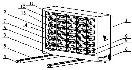
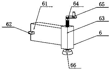
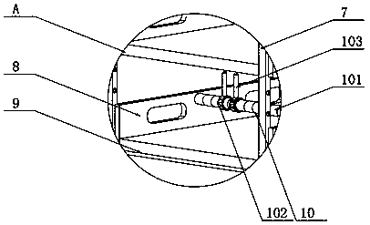
[0029] see Figure 1~4 , in an embodiment of the present invention, a mobile lifting compact shelf includes a compact shelf body 1, a guide rail sliding assembly, a support locking assembly 6, a partition 9, a hanging plate 8 and a column 7, wherein the compact shelf body 1 The bottom of the guide rail sliding assembly can slide and move along the extension direction of the guide rail sliding assembly. The support locking assembly 6 is arranged on the two sides of the guide rail sliding assembly on the compact shelf body 1, and the support locking assembly 6 pairs The compact shelf body 1 is supported so as to prevent it from sliding and moving on the guide rail sliding assembly, the compact shelf body 1 is provided with a plurality of partitions 9 arranged with adjustable vertical intervals, and it is characterized in that each The partitions 9 are arranged horizontally, and each of the partitions 9 is fixed with a plurality of hanging boards 8, and a plurality of parallel co...


PUM


Abstract

The invention discloses a movable lifting compact rack. According to the movable lifting compact rack, lifting assembles can be matched with hanging grooves in hanging plates on partition plates, andcorrespondingly the partition plates can be lifted and adjusted through the lifting assemblies; after adjustment is completed, the partition plates are fixed by pin shafts, and the operation is simpleand convenient; the distance between every two partition plates can be adjusted according to demands or the partition plates are lifted after files are arranged on the partition plates below, and theoperation is simple and convenient. According to the movable lifting compact rack, by arranging supporting and locking assemblies, the stability of a compact rack body is enhanced, the compact rack body can also be lifted at the same time, and the use convenience and safety of the compact rack body are improved; by arranging partition seats to limit the files, the stability of file placement is improved, the files are prevented from falling down, workers have no need to rearrange the files, and the workload and working strength of the workers are reduced.

Description

technical field [0001] The invention relates to the technical field of compact shelves, in particular to a mobile lifting compact shelf. Background technique [0002] Compact shelf, also known as dense cabinet, is a kind of intensive file installation. It can be understood and defined in this way: it is a shelf that installs axle wheels on the base of the double-sided fixed frame of the double column, and can move linearly along the small guide rail laid on the ground. Multiple shelves can be grouped together or separated as desired. [0003] At present, the stability of the commonly used compact shelves is not enough. The compact shelves are prone to dumping accidents due to inertia during the movement process, which is likely to cause injuries to the staff, cause damage to the compact shelves, and cause the compact shelves to be unusable, affecting the normal storage of files. The compact shelves The height cannot be adjusted, resulting in the bottom of the compact shelf ...

Claims


Application Information

Patent Timeline
Patent Type & Authority Applications(China)
IPC IPC(8): A47B63/06A47B57/06A47B91/06
Inventor 吴加琪
Owner 南京宇东科技发展有限公司
Why Eureka
Try Eureka