Multifunctional rope releasing equipment

A multi-functional, equipment-based technology, applied in rescue, escape equipment, and fire-fighting outside buildings, can solve problems such as fire hydrant doors being blocked by residents' sundries, incomplete fire-fighting facilities, and affecting rescue and fire-fighting speed and efficiency.

Inactive Publication Date: 2019-06-07
福州市晋安区澳榕自动化设备有限公司
View PDF0 Cites 0 Cited by
  • Summary
  • Abstract
  • Description
  • Claims
  • Application Information

AI Technical Summary

Problems solved by technology

There is also the arm-raising fire truck used in the existing fire-fighting and lifesaving, which can generally implement fire fighting and rescue at a height of 53 meters, and the climbing of the fire-fighting ladder truck has a limit. Usually, the fire-fighting ladder truck can only rise to 80 of the limit value. % or so, if the wind force on the ground reaches level 4 to 5, the fire-fighting aerial ladder truck will not be able to raise the operation. In this way, once a high-rise building above 50 meters catches fire or people are trapped, it will be difficult for the fire-fighting aerial ladder to play a role. Rely on one's own ability to escape, but some high-rise buildings have incomplete fire-fighting facilities, fire hydrant doors are blocked by residents with sundries and other phenomena, which bring resistance to fire-fighting and escape
In a word, when the height of the ladder truck is not enough, the fire rescue personnel are fully armed and go up the fire floor from the stairs to carry out fire fighting and rescue, which seriously affects the speed and efficiency of rescue and fire fighting. The existing technology has appeared on the roof layer or refuge floor of the building. Set up rope-releasing equipment. In case of fire, the above-mentioned rope-releasing equipment can be controlled to lower the slow-down rope and pull rope for emergency escape. However, the technical solution of the rope-releasing technique has certain safety risks, and also has the disadvantages of relatively complex structure and high cost. It has become necessary to study reliable and safe fire extinguishing, rescue and escape equipment outside the building

Method used


Image

  • Multifunctional rope releasing equipment
  • Multifunctional rope releasing equipment
  • Multifunctional rope releasing equipment

Examples


Embodiment Construction

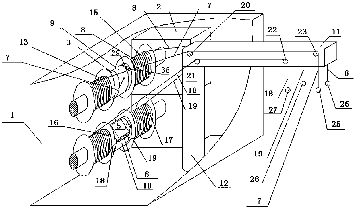
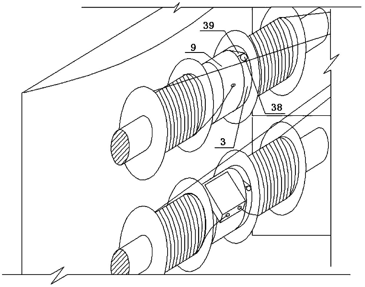
[0072] Such as figure 1 as shown, figure 1 It is a schematic oblique view of the multifunctional rope releasing device according to the first embodiment of the present application. The multifunctional rope releasing device includes a housing 1, an electric motor 2, a reel 3, a reel 5, a descender 6, a pull rope 7, a pull rope 8, a ring 9, a ring 10, a cantilever 11, and a column 12 , the above-mentioned electric motor 2, reel 3, reel 5, slow descender 6, stay rope 7, stay rope 8, ring 9, ring 10, column 12 are arranged in the housing, electric motor 2 and reel 3, The connection of the reel 5 can drive the reel 3 and the reel 5 to rotate. The above-mentioned ring 9 is set on the outer periphery of the reel 3 and can rotate around the reel 3. The above-mentioned ring 10 is set on the outer periphery of the reel 5 and can surround the reel 5 rotation, the above-mentioned descending device 6 is arranged on the ring 10, and one end of the above-mentioned stay rope 7 is fixedly co...


PUM


Abstract

The invention discloses multifunctional rope releasing equipment which comprises a power transmission system or a hydraulic transmission system or a pneumatic transmission system, a reel or a rotary shaft and a pull rope; a rotating shaft of a motor of the power transmission system or the hydraulic transmission system or the pneumatic transmission system can drive the reel or the rotary shaft to rotate; the reel or the rotary shaft is provided with a ring in a sleeved manner; the ring can rotate around the reel or the rotary shaft and is provided with a blocking surface; the reel or the rotaryshaft is provided with a blocking piece; one end of the pull rope is connected to the ring; the pull rope extends out of the ring, is wound around the reel or the rotary shaft and then extends out ofthe reel or the rotary shaft; a cable which is connected with the motor is connected with a power supply through a main contact and of a contactor; and a coil of the contactor is connected with a PLCand the power supply to form a loop.

Description

technical field [0001] The application belongs to a kind of outdoor fire extinguishing, rescue and escape equipment used in the construction field. Background technique [0002] Fires in high-rise buildings have always attracted people's attention, and the reliability of fire elevators in the event of a fire is worth pondering. There is also the arm-raising fire truck used in the existing fire-fighting and lifesaving, which can generally implement fire fighting and rescue at a height of 53 meters, and the climbing of the fire-fighting ladder truck has a limit. Usually, the fire-fighting ladder truck can only rise to 80 of the limit value. % or so, if the wind force on the ground reaches level 4 to 5, the fire-fighting aerial ladder truck will not be able to raise the operation. In this way, once a high-rise building above 50 meters catches fire or people are trapped, it will be difficult for the fire-fighting aerial ladder to play a role. Rely on one's own ability to escape...

Claims


Application Information

Patent Timeline
IPC IPC(8): A62B1/10A62B1/12A62B1/18A62C31/00
Inventor 不公告发明人
Owner 福州市晋安区澳榕自动化设备有限公司
Why Eureka
Try Eureka