Beam column decoration assembly in public place

A public place, beam-column technology, applied in covering/lining, building, building structure, etc., can solve the problem of inability to change the decoration structure, achieve the effect of improving the decoration effect and reducing the safety hazard

Active Publication Date: 2019-06-07
深圳市博大建设集团有限公司
6 Cites 0 Cited by

AI-Extracted Technical Summary

Problems solved by technology

However, regardless of the above methods, it is generally impossible to change ...

Abstract

The invention relates to a beam column decoration assembly in a public place. The beam column decoration assembly comprises a base frame unit and a display screen fixed to the outer side of the base frame unit, the base frame unit comprises a first frame body and a second frame body which are mutually buckled in a mode of surrounding a beam column, cambered surface supports which abut against thesurface of the beam column are arranged on the inner sides of the first frame body and the second frame body correspondingly, a second buckling unit with opening grooves facing the two sides is arranged at the end of the second frame body, and the first frame body is provided with a first buckling unit, wherein the first buckling unit and the second buckling unit are fixed in an buckled mode, andthe first buckling unit is used for sealing the opening grooves; and the surfaces of the outer sides of the first frame body and the second frame body are sunken towards the inner sides to form mounting grooves for allowing the display screen to be embedded. The beam column decoration assembly has the advantages that the surface of the outer side of the beam column is changed to be of a structurewith a decoration outer layer capable of being mounted, the cambered surface can be changed into the plane so as to adapt to mounting of the display screen, and the decoration effect is freely changedaccording to the need.

Application Domain

Technology Topic

Image

  • Beam column decoration assembly in public place
  • Beam column decoration assembly in public place
  • Beam column decoration assembly in public place

Examples

  • Experimental program(1)

Example Embodiment

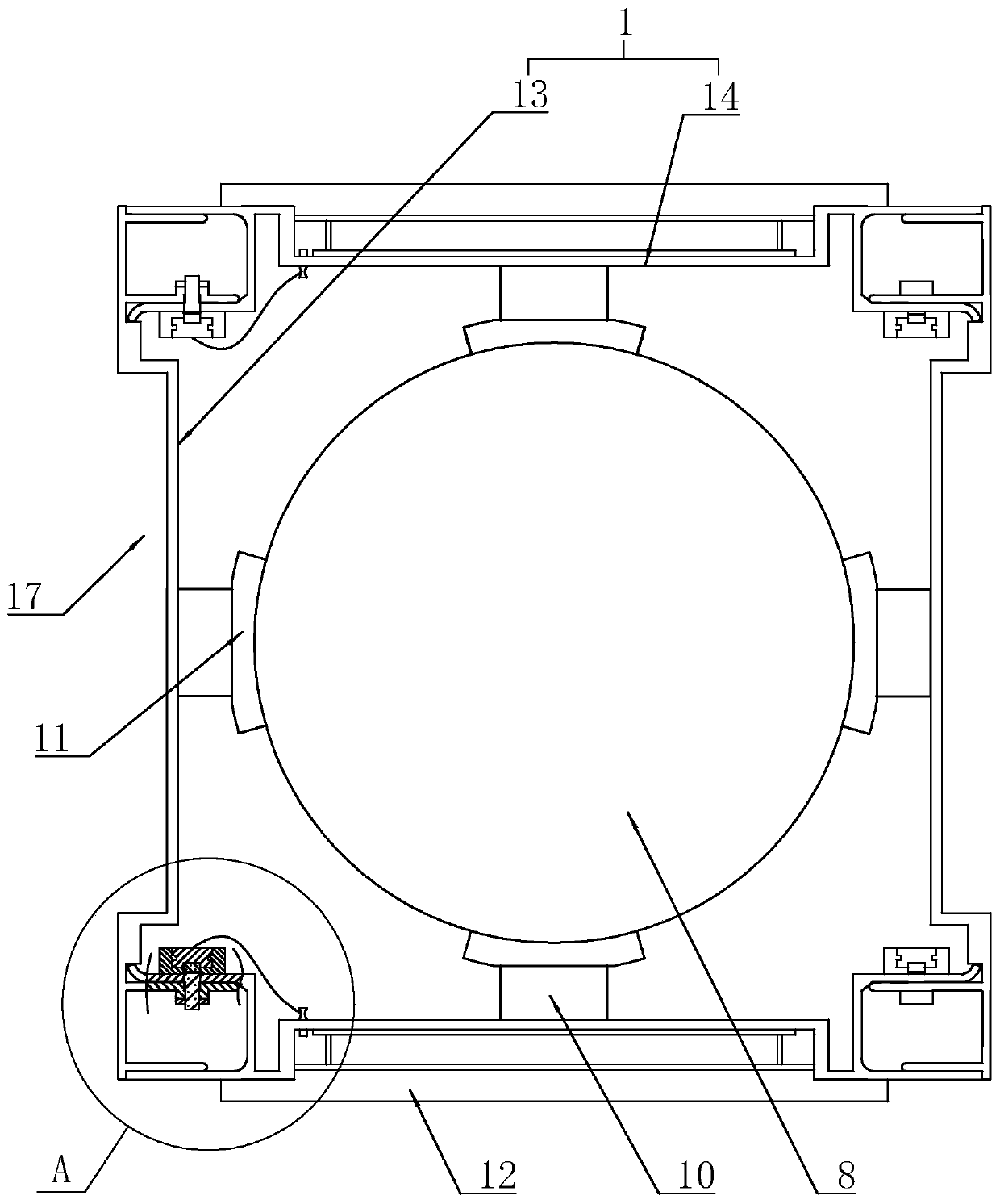
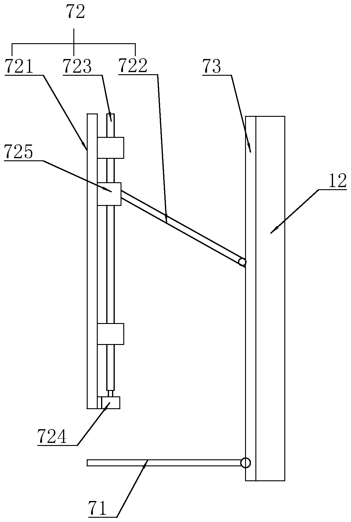
[0036] Example 1: A beam and column decoration assembly in public places, such as figure 1 with figure 2 As shown, the base frame unit 1 and the display screen 12 fixed to the outside of the base frame unit 1 are included. The outer surface of the base frame unit 1 is recessed inward to form a mounting groove 17 for the display screen 12 to be embedded. An upper frame 72, a lower frame 71, and a mounting frame 73 are arranged in the mounting slot 17, the display screen 12 is fixed to the mounting frame 73, the upper and lower ends of the mounting frame 73 are hinged to the upper frame 72 and the lower frame 71, and the lower frame 71 is connected to the mounting slot 17. Fixed connection. The upper frame 72 includes an inner frame 721 fixed to the inner wall of the mounting groove 17, an outer rod 722 with one end hinged to the mounting frame 73, a screw 723 rotatably connected to the inner frame 721, a drive motor 724 that drives the screw 723 to rotate, and a screw threaded connection with the screw 723 The adapter 725, the other end of the outer rod 722 is hinged to the adapter 725, and the inner side of the adapter is slidingly connected to the inner frame 721.
[0037] Reference figure 1 with image 3 , The base frame unit 1 includes a first frame body 13 and a second frame body 14 that are buckled to each other around the beam column 8, and the inner side of the first frame body 13 and the second frame body 14 are both provided with an arc abutting the surface of the beam column 8 Face support 11, the end of the second frame 14 is provided with a second buckling unit 16 with opening grooves facing both sides, and the first frame 13 is provided with a second buckling unit 16 that is buckled and fixed to the second buckle unit 16 and closes the opening groove First buckle unit 15.
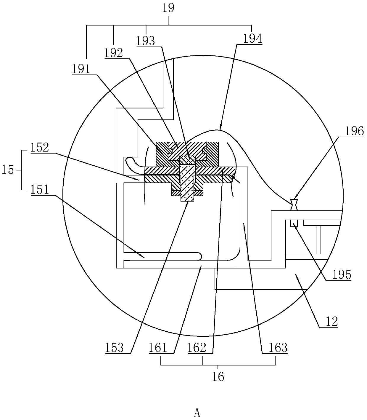
[0038] The first buckling unit 15 includes a first connecting plate 151 and a first limiting plate 152 protrudingly provided on the inner surface of the first frame body 13. The first limiting plate 152 slides vertically or diagonally. The limit piece 153, the end of the limit piece 153 is a magnetic end.
[0039] The second buckling unit 16 includes a second connecting plate 161 that abuts on the surface of the first connecting plate 151 on the side away from the first limiting plate 152, and a side of the first limiting plate 152 away from the first connecting plate 151. The second limit plate 162 abutting on the surface and the connecting plate 163 connecting the second connecting plate 161 and the second limit plate 162; the second limit plate 162 is provided with a second limit through which the limit member 153 passes Slot and magnetic attraction assembly 19 that magnetically attracts the limiting member 153 into the second limiting slot.
[0040] The magnetic attraction assembly 19 includes a sliding groove 191 fixed on the side of the second limiting plate 162 away from the first limiting plate 152, a sliding bar 192 slidably disposed in the sliding groove 191, and magnets 193 fixed to the sliding bar 192 at intervals, The magnetic poles of two adjacent magnets 193 facing the first limiting plate 152 are opposite. One end of the sliding bar 192 is fixed with a drawstring 194, and the installation slot 17 of the first frame 13 is provided with a knob 195. The knob 195 passes through the first frame 13 and is provided with a winding wheel 196 inside the first frame 13. One end of the draw rope 194 is fixed to the reel 196.
[0041] Reference figure 1 , The arc support 11 and the base frame unit 1 are connected by an omnidirectional adjustment joint mechanism 10. Reference Figure 4 with Figure 5 , The connecting mechanism includes a sliding track 7 located on the surface of the mounting groove 17 on the side close to the beam column 8, a horizontal carrier connected to the sliding track 7 in horizontal sliding motion 2, and the horizontal carrier 2 tightly fixed to the first part of the rack. The tightening component, the lifting carrier 3 connected to the horizontal carrier 2 by sliding up and down, the second tightening component that fastens the lifting carrier 3 to the horizontal carrier 2, one end is fixed to the lifting carrier 3 and the other end is relative to the lifting The first rotating component 4 that the carrier 3 rotates or tightens on the vertical plane, the second rotating component 5 whose one end is fixed to the first rotating component 4 and the other end rotates or tightens on a horizontal plane relative to the first rotating component 4, arc A back fixing frame 6 is fixed on the back of the face support 11, and the back fixing frame 6 is fixed to the second rotating assembly 5.
[0042] The horizontal carrier 2 includes a guide rail 22 for sliding the lifting carrier 3 and a sliding member 23 fixed to the guide rail 22. The sliding member 23 includes a T-shaped convex portion 231 and a wing portion 232. The wing portion 232 is slidably embedded in the sliding track 7 of the base frame unit 1 and faces the end surface of the convex portion 231 and the base frame unit. The sliding track 7 of 1 abuts, the convex portion 231 protrudes from the sliding track 7, and the side of the wing portion 232 facing the convex portion 231 is provided with a non-slip tooth surface 233.
[0043] The first fastening component is a first fastening screw 21 passing through the convex portion 231 and abutting on the inner wall of the sliding rail 7 with one end. The first fastening screw 21 is threadedly connected to the convex portion 231, and the convex portion 231 is provided with For the countersunk hole for the nut to be inserted into, both ends of the protruding portion 231 along the length direction are provided with the first set screw 21. During installation, the first set screw 21 is adjusted to the maximum elongation relative to the sliding member 23, and the end surfaces of the two wing portions 232 facing the convex portion 231 abut the inner wall of the guide rail 22.
[0044] The lifting carrier 3 includes a lifting plate 32 that is slidably connected to the guide rail 22. A plurality of positioning holes 33 are distributed on the lifting plate 32 along the sliding direction. The second tightening assembly includes two upper and lower second fastening components that penetrate the guide rail 22. Two positioning screws 31, the second positioning screw 31 is threadedly connected with the positioning hole 33, and the height adjustment can be realized by the second positioning screw 31 butting with different positioning holes 33.
[0045] The first rotating assembly 4 includes an angle frame 41 fixed to the lifting plate 32 and a first rotating frame 42 that is plug-connected to the angle frame 41. The first rotating frame 42 is provided with an adjusting slot 43, and the side wall of the angle frame 41 is provided There are two arc-shaped grooves 44 distributed up and down. The side of the first turret 42 is provided with fasteners 45 that pass through the first turret 42 and the adjusting groove 43 and fix the first turret 42 and the angle frame 41. . Various angles of the first rotating frame 42 relative to the angle frame 41 can be adjusted by adjusting the two-point combination at different positions of the double arc-shaped slot 44.
[0046] The second rotating assembly 5 includes a second fixing plate 51 fixed to the first rotating frame 42, a second sleeve 52 fixed to the second fixing plate 51, and a second rotating member 53 fixed to the hanging plate 62. The second rotating member 53 is clamped on the two axial ends of the second sleeve 52 and pre-tightened by a damping screw 54 passing through the second sleeve 52 in the axial direction and a damping nut 55 threadedly connected to the end of the damping screw 54. The tightness of the damping screw 54 and the damping nut 55 is adjusted to adjust the damping effect of the second rotating assembly 5 or to fix the second rotating member 53.
[0047] The back fixing frame 6 includes a receiving plate 61 fixed to the back of the arc support 11 and a hanging plate 62 fixed to the second rotating assembly 5. The receiving plate 61 is fixed with a pawl 63, a first mother stack 64 and a first screw 72365 rotatably connected to the first mother stack 64, and the hanging plate 62 is slidably connected to the moving track formed by the two pawls 63. The top of the hanging plate 62 is provided with a first sub-stack 66 threadedly connected with the first screw 72365. The two sides of the bottom of the hanging plate 62 are protrudingly provided with anti-dropping portions 67 that abut the claw 63 along the sliding direction of the hanging plate 62. The anti-dropping part 67 can play a role of lifting during the initial installation, and the sliding combination between the hanging plate 62 and the receiving plate 61 is matched with the relative up and down adjustment of the screw connection.
[0048] Installation method:
[0049] Pre-installation, abut the arc support 11 and the beam column 8, and adapt the position and angle of the arc support 11 through the horizontal carrier 2, the lifting carrier 3, the first rotating assembly 4, and the second rotating assembly 5. Adjust so that the surface of the arc support 11 is attached to the surface of the beam and column 8; then the second frame 14 and the corresponding arc support 11 are attached to the surface of the beam and column 8, the first frame 13 is installed, and the first The buckle unit is connected to the second buckle unit 16, and the position of the slider 192 of the magnetic attraction assembly 19 is adjusted by the knob 195 to draw the limit member 153 into the second limit slot.

PUM

no PUM

Description & Claims & Application Information

We can also present the details of the Description, Claims and Application information to help users get a comprehensive understanding of the technical details of the patent, such as background art, summary of invention, brief description of drawings, description of embodiments, and other original content. On the other hand, users can also determine the specific scope of protection of the technology through the list of claims; as well as understand the changes in the life cycle of the technology with the presentation of the patent timeline. Login to view more.

Similar technology patents

System, method and device for execution of payment business

ActiveCN107038560AReduce waiting timeReduce security risksCredit schemesElectronic credentialsOperating systemPayment
Owner:ADVANCED NEW TECH CO LTD

Classification and recommendation of technical efficacy words

  • Reduce security risks
  • Improve the decorative effect

Automatic driving system

Owner:CHERY AUTOMOBILE CO LTD

Power safety socket device

Owner:东莞科奔电器有限公司
Why Eureka
Try Eureka