Supercharge Your Innovation With Domain-Expert AI Agents!

Automatic tubing and sucker rod clamping shackle device for oil field workover treatment

A technology for pipe rods and workovers, applied in drill pipe, drill pipe, casing and other directions, can solve the problems of high labor intensity, difficult operation and construction conditions, low safety operation coefficient, etc., and achieve the effect of improving efficiency

Pending Publication Date: 2019-06-07
PETROCHINA CO LTD
View PDF0 Cites 2 Cited by
  • Summary
  • Abstract
  • Description
  • Claims
  • Application Information

AI Technical Summary

Problems solved by technology

[0002] The downhole workover operation process of the oil field is the operation process of repairing or overhauling the oil well. The labor intensity is high, the operation and construction conditions are difficult, the coefficient of safe operation is low, and it is easy to cause casualties. Therefore, the study of workover operations automation is necessary
[0003] An important task in the workover operation is to disassemble, disengage or install and lock the oil pipe or oil rod imported from the well. At present, the disassembly and installation of the oil pipe or oil rod is carried out by lifting the oil pipe or oil rod. Then turn it with a wrench to disassemble or install it, which is inefficient and easy to cause personal injury

Method used


Image

  • Automatic tubing and sucker rod clamping shackle device for oil field workover treatment
  • Automatic tubing and sucker rod clamping shackle device for oil field workover treatment
  • Automatic tubing and sucker rod clamping shackle device for oil field workover treatment

Examples


Embodiment Construction

[0076] In order to further explain the technical means and effects of the present invention to achieve the intended purpose of the invention, the specific implementation, structure, features and effects of the application according to the present invention will be described in detail below in conjunction with the accompanying drawings and preferred embodiments. . In the following description, different "one embodiment" or "embodiment" do not necessarily refer to the same embodiment. Furthermore, the particular features, structures, or characteristics of one or more embodiments may be combined in any suitable manner.

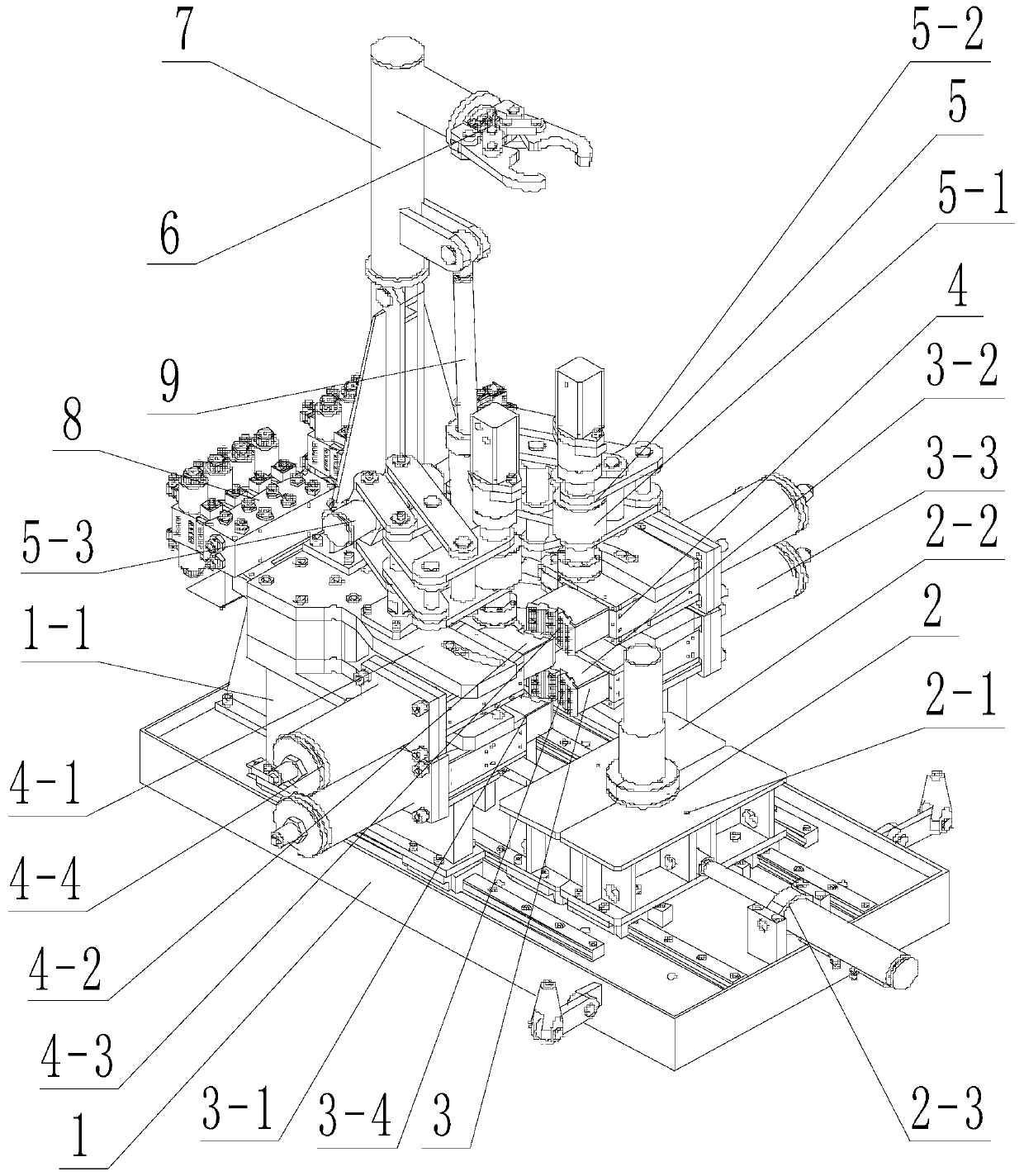
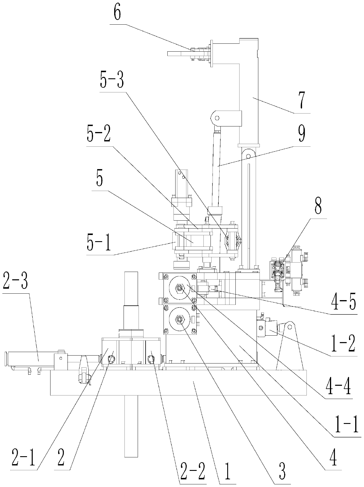
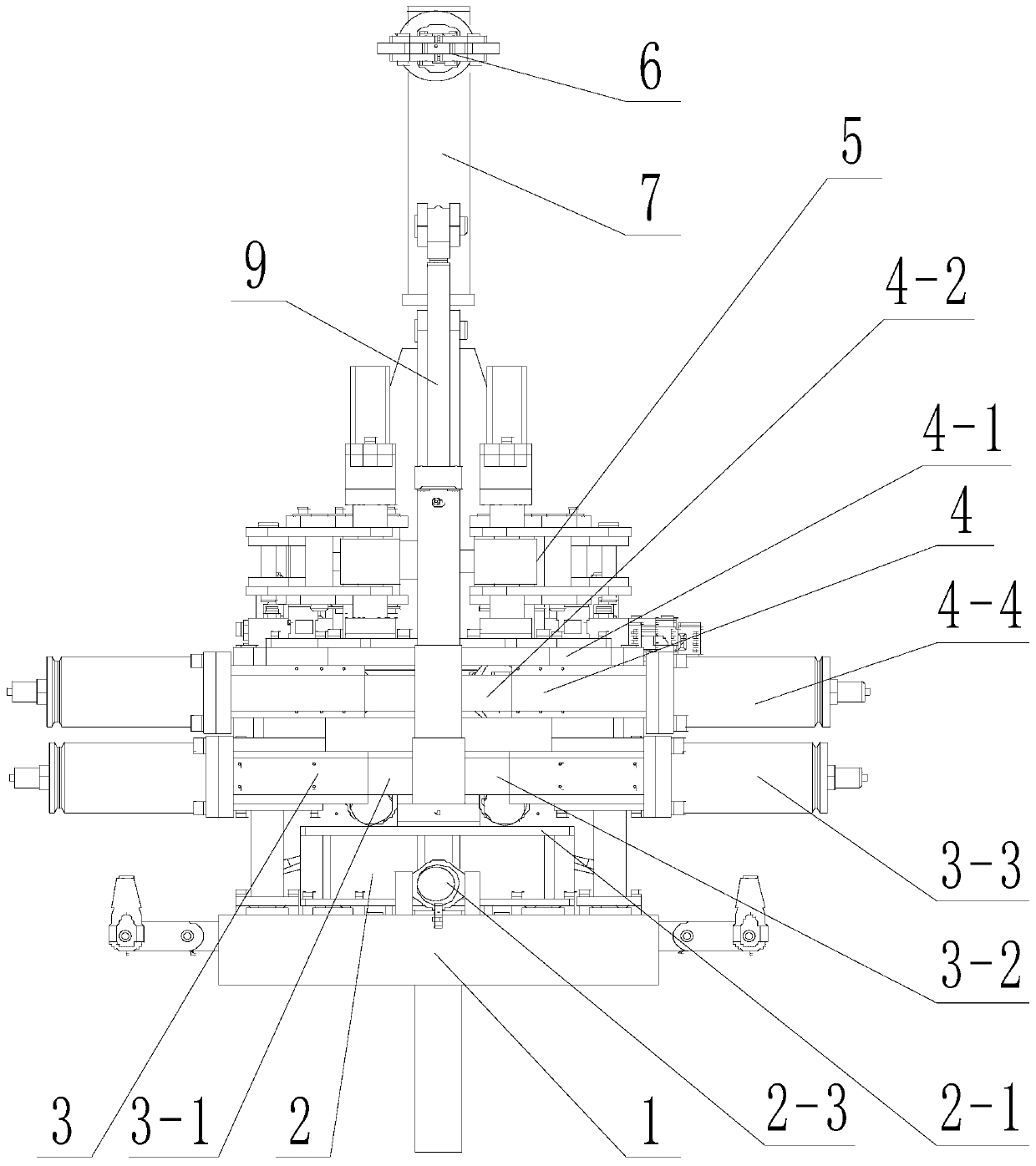
[0077] Such as Figure 1 to Figure 4 As shown, an embodiment of the present invention proposes a pipe rod automatic tightening and breaking device for oil field workover operations, comprising: a support 1, a positioning mechanism 2, a clamping mechanism 3, a flushing mechanism 4, a tightening and unfastening mechanism Buckle mechanism 5 and control system 8; s...


PUM


Abstract

The invention relates to the technical field of oil field exploitation, in particular to an automatic tubing and sucker rod clamping shackle device for oil field workover treatment. The automatic tubing and sucker rod clamping shackle device for the oil field workover treatment comprises a support seat, a positioning mechanism, a clamping mechanism, a buckle punching mechanism, a clamping shacklemechanism and a control system; the positioning mechanism arranged on the support seat is used for supporting a pipe clamp of the lower end of the tubing and sucker rod to be unloaded or locked; the clamping mechanism is arranged on the support seat, located on the upper part of the positioning mechanism, and is used for clamping the pipe clamp of the lower end of the tubing and sucker rod to be unloaded or locked; the buckle punching mechanism is arranged on the support seat, located on the upper part of the clamping mechanism, and is used for clamping and rotating the tubing and sucker rod to be unloaded or locked; the clamping shackle mechanism is arranged on the support seat, located on the upper part of the buckle punching mechanism, and used for clamping the surface of the tubing andsucker rod to be unloaded or locked and rotating the clamped the tubing and sucker rod; and the control system is arranged on the support seat and is used for controlling the actions of the positioning mechanism, the clamping mechanism, the buckle punching mechanism and the clamping shackle mechanism. According to the automatic tubing and sucker rod clamping shackle device for oil field workovertreatment, the efficiency of installation and unloading of the tubing or sucker rods can be improved.

Description

technical field [0001] The invention relates to the technical field of oilfield exploitation, in particular to an automatic tightening and breaking device for pipes and rods used in oilfield workover operations. Background technique [0002] The downhole workover operation process of the oil field is the operation process of repairing or overhauling the oil well. The labor intensity is high, the operation and construction conditions are difficult, the coefficient of safe operation is low, and it is easy to cause casualties. Therefore, the study of workover operations Automation is very necessary. [0003] An important task in the workover operation is to disassemble, disengage or install and lock the oil pipe or oil rod imported from the well. At present, the disassembly and installation of the oil pipe or oil rod is carried out by lifting the oil pipe or oil rod. Then it is rotated and disassembled or installed by a wrench, which is inefficient and can easily cause persona...

Claims


Application Information

Patent Timeline
IPC IPC(8): E21B19/16
Inventor 谢建勇刘庆新叶俊华范杰张辉许春河
Owner PETROCHINA CO LTD
Features
  • R&D
  • Intellectual Property
  • Life Sciences
  • Materials
  • Tech Scout
  • Unparalleled Data Quality
  • Higher Quality Content
  • 60% Fewer Hallucinations
Learn More