Novel heat exchanger capable of automatically adjusting heat exchange area and flow adjusting method

An automatic adjustment and heat exchange area technology, applied in the direction of indirect heat exchangers, heat exchanger types, heat exchange equipment, etc., can solve the problem of affecting subsequent processes, energy consumption of water pumps, and the inability of condensers to make changes according to real-time working conditions, etc. problem, to achieve the effect of precise regulation of heat exchange area and reduction of usage

Pending Publication Date: 2019-06-07
JILIN UNIV
View PDF0 Cites 5 Cited by
  • Summary
  • Abstract
  • Description
  • Claims
  • Application Information

AI Technical Summary

Problems solved by technology

However, in reality, users have different power consumption demands at different times of the day, and the load of the grid changes accordingly, and the load of the steam turbine is also changing, resulting in the change of exhaust steam flow, and the difference between day and night is large
The condenser cannot make changes according to real-time working conditions, which will cause the fluid outlet temperature to deviate from the design value and affect the subsequent process
At the same time, the fluid consumption of the tube side increases, and the water pump also consumes unnecessary energy.

Method used


Image

  • Novel heat exchanger capable of automatically adjusting heat exchange area and flow adjusting method
  • Novel heat exchanger capable of automatically adjusting heat exchange area and flow adjusting method
  • Novel heat exchanger capable of automatically adjusting heat exchange area and flow adjusting method

Examples


Embodiment Construction

[0070] The present invention will be further described in detail below in conjunction with the accompanying drawings, so that those skilled in the art can implement it with reference to the description.

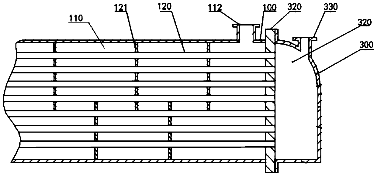
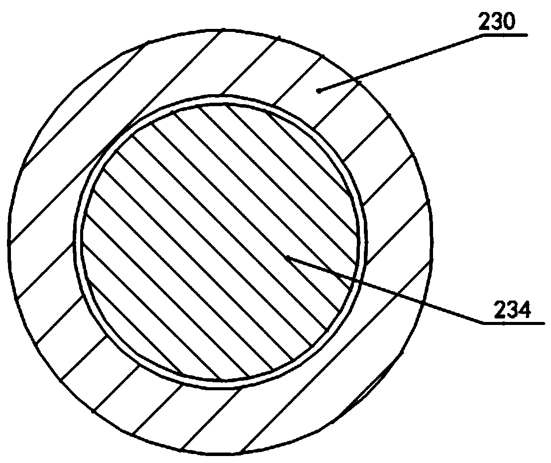
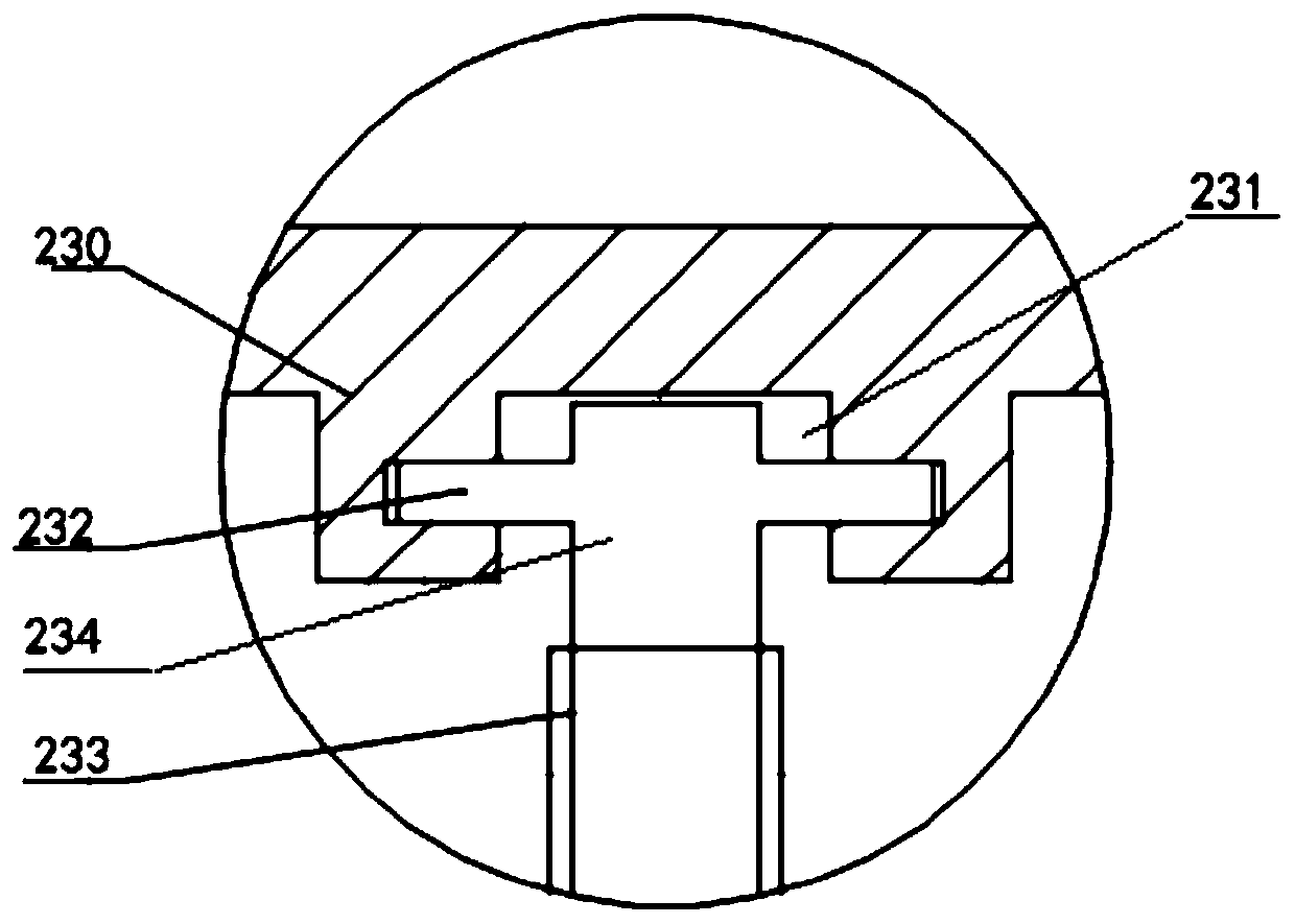
[0071] Such as Figure 1-6 As shown, the present invention provides a new type of heat exchanger that automatically adjusts the heat exchange area, including: a shell 100; and a first tube box 200 and a second tube box 300, which are symmetrically arranged on both sides of the shell 100 in the axial direction; A first sealing plate 210 and a second sealing plate 310 are respectively sealed between the axial sides of the housing 100 and the first tube box 200 and the second tube box 300, and the housing 100, the first tube box 200 and the second tube box 300 are sealed. The second pipe box 300 is divided into a shell chamber 110, a first pipe box chamber 220, and a second pipe box chamber 320; heat exchange tubes 120 are arranged in parallel at equal intervals in the shell 100...


PUM


Abstract

The invention discloses a novel heat exchanger capable of automatically adjusting a heat exchange area. The heat exchanger comprises a shell, a first channel and a second channel symmetrically arranged on two axial sides of the shell, a first sealing plate and a second sealing plate symmetrically sealed on two axial sides of the shell for dividing the shell, the first channel and the second channel into a shell cavity, a first channel cavity and a second channel cavity, heat exchange pipes arranged in the shell in parallel at equal intervals and communicating with the first channel cavity andthe second channel cavity by two ends, a piston arranged in the first channel cavity and tightly contacted with the inner wall of the first channel cavity in the peripheral direction and capable of moving in the axial direction of the first channel cavity, and a driving mechanism connected with the piston by an output end and used for driving the piston to move in the axial direction of the firstchannel cavity. The invention further provides a flow adjusting method of the novel heat exchanger capable of automatically adjusting the heat exchange area; the heat exchange is guaranteed; and the energy is saved.

Description

technical field [0001] The invention relates to the technical field of heat exchangers, and more specifically, the invention relates to a novel heat exchanger with automatic heat exchange area adjustment and a flow adjustment method. Background technique [0002] A heat exchanger is a commonly used process equipment for heat exchange. The shell and tube heat exchanger is a partitioned wall heat exchanger that uses the wall of the tube bundle enclosed in the shell as the heat transfer surface. This kind of heat exchanger has simple structure, low cost, wide cross-section, easy to clean scale, can be made of various structural materials (mainly metal materials), and can be used under high temperature and high pressure. It is the most widely used type at present. [0003] Taking thermal power generation as an example, heat exchangers are essential equipment. Most of the condensers used now are condensers with a fixed heat exchange area. However, in reality, users have differ...

Claims


Application Information

Patent Timeline
Patent Type & Authority Applications(China)
IPC IPC(8): F28D7/16F28F27/02
Inventor 金英爱蒋代晖袁昊瑞闫泽宇陈彦宇马纯强
Owner JILIN UNIV
Why Eureka
Try Eureka