
Vehicle-mounted lens sealing test device

A test device and sealing technology, which is applied in the direction of liquid tightness measurement by using liquid/vacuum degree, by measuring the increase and decrease rate of fluid, etc., can solve the problems of long test period, cumbersome operation steps, and easy to suffer from pressure loss, etc. To achieve the effect of eliminating pressure loss, simplifying the detection steps and shortening the test cycle

Pending Publication Date: 2019-06-07
SIRTEC INT SUZHOU
View PDF0 Cites 1 Cited by
  • Summary
  • Abstract
  • Description
  • Claims
  • Application Information

AI Technical Summary

Problems solved by technology

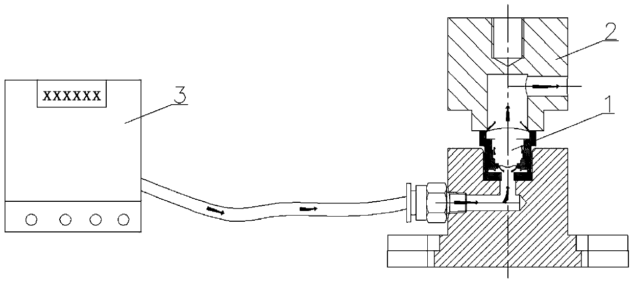
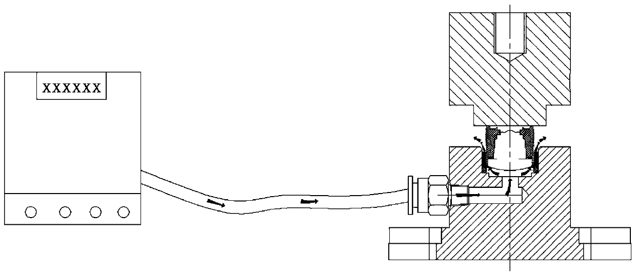
In the current sealing test procedure, the sealing part of the lens base and the lens gland and the sealing part of the lens base and the lens gland must meet the IP69K waterproof requirement at the same time. In the prior art, the sealing test device is an airtight tester Carry out single-channel detection, however, a single test can only detect the sealing condition of one of the sealing parts of the lens, and it is necessary to re-exchange the orientation of the vehicle-mounted lens during the conversion of the two test processes (such as figure 2 , 3 shown in ), so that the test operation steps are very cumbersome and the test cycle is longer, which increases the production cost of the vehicle lens
In addition, during the test process, the on-board lens and the detection body are in rigid contact, which is very vulnerable to pressure loss. Therefore, it is urgent for technicians to solve the above problems

Method used


Image

  • Vehicle-mounted lens sealing test device
  • Vehicle-mounted lens sealing test device
  • Vehicle-mounted lens sealing test device

Examples


Embodiment Construction

[0028] In the description of the present invention, it should be understood that the orientation or positional relationship indicated by the terms "inner", "outer", "upper", "lower" etc. is based on the orientation or positional relationship shown in the drawings, and is only for It is convenient to describe the present invention and simplify the description, but does not indicate or imply that the device or element referred to must have a specific orientation, be constructed and operate in a specific orientation, and thus should not be construed as limiting the present invention.

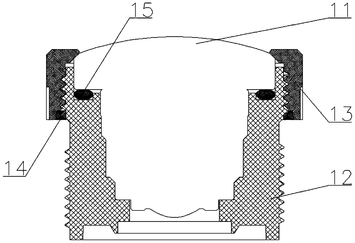
[0029] In order to facilitate those skilled in the art to understand the sealing test device disclosed in the present invention, before proceeding to the formal description, the structure of the vehicle-mounted lens 1 is first briefly described, specifically as follows: the vehicle-mounted lens 1 is composed of a lens 11, a lens base 12 and The lens gland 13 is composed of several parts, wherein the...


PUM


Abstract

The invention relates to the technical field of test equipment, in particular to a vehicle-mounted lens sealing test device. The vehicle-mounted lens sealing test device comprises a detection body andan air-sealing tester matched with the detection body, wherein the detection body is composed of a base and an upper pressing part. A cavity is formed in a joint transition position between the baseand the upper pressing part, and an extrusion abutting part is arranged in the cavity. Before a sealing test is carried out, the upper pressing part moves downwards until the cavity forms into a sealed cavity, and at the same time, elastic deformation of the extrusion abutting part occurs so that the extrusion abutting part abuts against a vehicle-mounted lens. A test air passage is arranged in the upper pressing part, so that two sealing parts on the vehicle-mounted lens are in communication with the air-sealing tester. Through the way, on one hand, the vehicle-mounted lens is fixed through the elastic deformation action of the extrusion abutting part, and thus the pressing loss of the vehicle-mounted lens is eliminated; and on the other hand, the sealing condition of the two sealing parts can be detected at the same time through one test process, and the orientation of the vehicle-mounted lens during the test process does not need to be changed.

Description

technical field [0001] The invention relates to the technical field of testing equipment, in particular to a vehicle-mounted lens sealing test device. Background technique [0002] Car lenses require a certain level of waterproofing, because when the camera is in a humid environment, water vapor and dust can easily enter the protective case, resulting in fogging, dust, and damage to the device. Therefore, the manufacturer will test the airtightness of the car lens to determine whether the product meets the waterproof level requirements. In the current sealing test procedure, the sealing part of the lens base and the lens gland and the sealing part of the lens base and the lens gland must meet the IP69K waterproof requirement at the same time. In the prior art, the sealing test device is an airtight tester Carry out single-channel detection, however, a single test can only detect the sealing condition of one of the sealing parts of the lens, and it is necessary to re-exchang...

Claims


Application Information

Patent Timeline
Patent Type & Authority Applications(China)
IPC IPC(8): G01M3/26
Inventor 罗艳波杨井留汪磊耿永飞
Owner SIRTEC INT SUZHOU
Learn More