
Ultrasonic positioning device for unmanned aerial vehicles and positioning method thereof

A technology of ultrasonic positioning and positioning method, which is applied in directions such as beacon systems using ultrasonic/sonic/infrasonic waves, which can solve the problems of difficulty in realizing the reference point of the known position and the high cost of RTK technology, and achieve the effect of efficient positioning.

Pending Publication Date: 2019-06-07
STATE GRID TIANJIN ELECTRIC POWER +1
View PDF5 Cites 4 Cited by
  • Summary
  • Abstract
  • Description
  • Claims
  • Application Information

AI Technical Summary

Problems solved by technology

Real-time dynamic measurement technology RTK (Real Time Kinematic) can improve the positioning progress, but during the measurement process, RTK still needs to use GPS to locate the reference point with known accurate coordinates, and then calibrate the position of the UAV to work in the field. Fiducials with known positions are often difficult to achieve and RTK technology is expensive

Method used


Image

  • Ultrasonic positioning device for unmanned aerial vehicles and positioning method thereof
  • Ultrasonic positioning device for unmanned aerial vehicles and positioning method thereof
  • Ultrasonic positioning device for unmanned aerial vehicles and positioning method thereof

Examples


Embodiment Construction

[0023] The present invention will be further described in detail below in conjunction with the accompanying drawings and through specific embodiments. The following embodiments are only descriptive, not restrictive, and cannot limit the protection scope of the present invention.

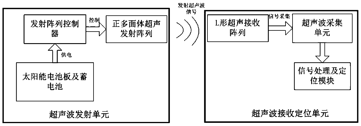
[0024] An ultrasonic positioning device for an unmanned aerial vehicle, comprising an ultrasonic transmitting unit installed on a power transmission line tower, and an ultrasonic receiving and positioning unit installed on an unmanned aerial vehicle.

[0025] The ultrasonic transmitting unit installed on the power transmission line tower includes a regular polyhedral ultrasonic transmitting array, a transmitting array controller, a solar panel and a storage battery connected in sequence. The above-mentioned devices are mounted on the housing through the frame.

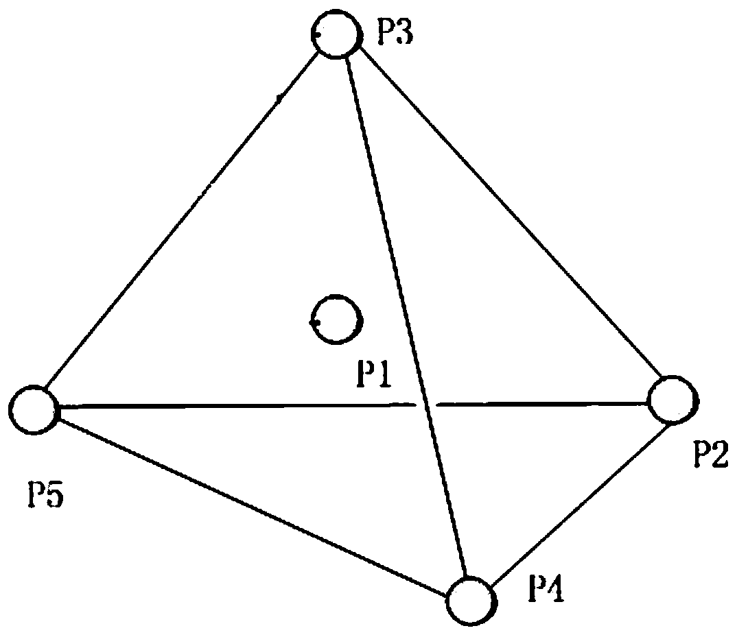
[0026] The regular polyhedron ultrasonic emission array can be a regular tetrahedron emission array, with 1 array element in the center and ...


PUM


Abstract

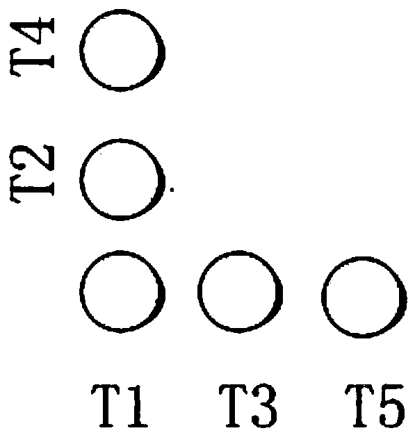
The invention relates to an ultrasonic positioning device for unmanned aerial vehicles and a positioning method thereof. The positioning device comprises an ultrasonic transmitting unit installed on atransmission line tower and an ultrasonic receiving and positioning unit installed on an unmanned aerial vehicle. The ultrasonic transmitting unit comprises a regular polyhedral ultrasonic transmitting array, a transmitting array controller, a solar cell panel and a storage battery connected in turn. The ultrasonic receiving and positioning unit comprises an L-shaped ultrasonic receiving array, an ultrasonic acquisition unit and a signal processing and positioning module connected in turn. Through the special design of the ultrasonic transmitting array and the receiving array, the communication between the transmitting part and the receiving and positioning part is not needed. The transmitting part transmits signals all the time, and the receiving part installed on the unmanned aerial vehicle can complete positioning only by receiving signals. Therefore, positioning is realized efficiently.

Description

technical field [0001] The invention belongs to the field of multi-rotor unmanned aerial vehicles, and relates to spatial positioning of unmanned aerial vehicles, in particular to an ultrasonic positioning device and a positioning method of a multi-rotor unmanned aerial vehicle for patrolling power transmission lines. Background technique [0002] With the gradual expansion of the scale of the power grid and the rapid increase in the amount of transmission line equipment, the traditional manual inspection can no longer meet the demand, especially in the western region of my country, where there are many mountains and rivers, the workload of manual inspection is difficult, and the inspection efficiency is low. [0003] In recent years, the UAV intelligent inspection technology has developed rapidly, and it is not affected by the terrain. It patrols along the transmission line, which greatly improves the inspection work efficiency, and the UAV can carry different advanced airbo...

Claims


Application Information

Patent Timeline
IPC IPC(8): G01S1/76G01S1/72
Inventor 辛晓虎王建慧李赢李延生肖建超宋晓博胡泉伟冯焕阳贾建华王海超
Owner STATE GRID TIANJIN ELECTRIC POWER
Learn More